This thread has been locked.

If you have a related question, please click the "Ask a related question" button in the top right corner. The newly created question will be automatically linked to this question.

TMS320F28388D: F28388D ADC differential sample

Part Number: TMS320F28388D

When testing the demo of adc_ex1_soc_software that comes with it

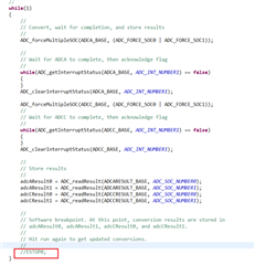
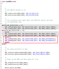
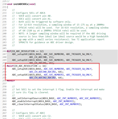
When F28388D multi-channel ADC performs differential and single sampling, give ADCA 1 channel 1.5V voltage, 2 channels are not connected to the voltage, and left open, the values of channels 1, 2 are basically the same. But it is normal for single-ended sampling How do I set it up? The following figure shows the process of changing the single-ended sampling in the demo to differential sampling, and the final test result.

  • Dear team:

    I compiled this routine and found that when I change the macro definition

    #define EX_ADC_RESOLUTION 12

    to

    #define EX_ADC_RESOLUTION 16

    4 errors will be reported:

    "../adc_ex1_soc_software.c", line 203: error #31: expression must have integral type

    To change ADC resolution from 12 bits to 16 bits, do you need to modify anything besides macro definition?

    Best regards

  • Hi,

    The results that you are seeing for the open pin can be of the tri state voltage. If you have a multimeter or any other way to check the analog voltage seen on the pin, you can verify the voltage on that particular pin.

    Thanks,

    Aditya

  • Hi Green,

    Thanks for bringing this up. Seems to be some sort of compilation bug. Let me check this out and clean this for next release.

    Aditya

  • I measure the pin ADCA 2 channel that  is not connected to the voltage source with multimeter , the result is as you say, there is  tri state voltage

    on the pin . from my perspective, unused ADC channel's voltage should be zero. and sometimes ''unused ADC channel'' also be used when application is running , and if ADCA  is configured as single-ended, above event is disappeared. so how do I configure the F28388D ADC as differential mode to avoid  tri state voltage.

  • I am not sure why do you want to keep the pin open in the differential state. You can anyways connect it to the zero voltage available on the board or even using the software GPIO configurations, you can keep it at zero voltage.

    Any reason to keep it open?

    Thanks,

    Aditya

  • Hi

    Do you know how to do “ using the software GPIO configurations”?

  • You can use "GPIO_writePin()" API available with the gpio driver. Reference can be taken from adc_ex4 for rebuilding it to your setup.

    Thanks,

    Aditya

  • I think your explanation is right , thanks for your patient help ,Now another issue occured to me,I measured wire voltage form my own design board that connect to ADC pin directly , the multi meter show the value is right ,but debug value in css is wrong ,difference between two values is about 0.16V,if the difference  value is small ,I can  Calibration ADC , but now difference  value is large , maybe  some  exceptions affected the ADC . Same software application download to  kit board , debug value is very precise.  so I don't know why ,do you have any ideas?

  • Hi,

    Sorry I didn't fully get what you described. So, as I understand, you are connecting an external signal to the ADC input pin and validating the voltage which is 0.16V different. Can you check with other ADC channel as well once so that we can confirm the issue?


    Same software application download to  kit board , debug value is very precise.

    Can you elaborate the marked point? 

    Thanks,

    Aditya

  • Sorry I didn't fully get what you described. So, as I understand, you are connecting an external signal to the ADC input pin and validating the voltage which is 0.16V different. Can you check with other ADC channel as well once so that we can confirm the issue?

    you got it right.

    Can you elaborate the marked point? 

    I buy the development  board form TI website,and same software download to  development  board, the ADC value is precise compare to our design board. and   i think the software is right. 

    so I don't know why? any special configuration about hardware ,do you have ever encounter a similar problem ?

  • I may not be the best person to answer your question relating to the hardware issue on your board. But, what I can tell is that the ADC module will remain same on your board and the development board as well. The path resistance and other impedances to the ADC input will decide the precision with which the ADC samples the signal.

    TI boards are tested functionally and with the software to ensure no or minimal difference in the desired output. You may want to check your development board for any hardware issues.

    Thanks,

    Aditya