This thread has been locked.

If you have a related question, please click the "Ask a related question" button in the top right corner. The newly created question will be automatically linked to this question.

TMS320F28335: ADC cant sample correctly at high and decimal values of frequency

Part Number: TMS320F28335
Other Parts Discussed in Thread: TMDSCNCD28335, C2000WARE

Hi all,

For starting I have been trying to implement an FIR filter using DMA registers as explained in lab 9 at the TI F28335 controller workshop. I tried to sample a sinusoid of different frequencies and checked ADCBUF register values The values get distorted at higher frequencies greater than 2-3Khz also at decimal values like the ADCBuf waveform as in graph in CCS came right for 1 and 2 kHz but gave wrong values for 1.1 kHz,1.2 kHz.The sampling frequency is high at 48Khz.by epwm2. This should not have happened theoretically but still, I got a distorted sin wave at such a low frequency compared to the sampling frequency

I wanted to implement my own FFT code thus I needed the ADCBUF register correct so that I could detect a fault in my current signal.

Can someone explain why the ADCBUF waveform gets distorted at high or decimal-like frequencies?

Regards 

Nitesh Mahawar

  • Nitesh,

    Thanks for reaching out to the E2E forum.  Can you comment on your hardware, is it the TMDSCNCD28335 control CARD or is it some custom HW with our MCU?  Given that the PWM is at a >> sample rate vs your signal of interest I would also look at the signal source with a scope to make sure that it looks clean from that perspective and is within the bounds of the ADC voltage wise(0V-3.3V).

    The other component is that while the PWM rate is tied to the ADC trigger/sample rate; the ADC itself has its own configuration in terms of clock rate(HSPCLK) and interna clock dividers.  If you are basing your code off our examples in C2000Ware, likely the ADC is set to run at its max of 25MHz clock, which supports up to 80ns between samples.

    It may be easier if you take a screen shot of both the ADC registers and the SysCtrl registers and post them here, so I can confirm the relative clocks.  If you are using HW that is different than the control card, I would need to know your input clock as well.

    Best,
    Matthew

  • Hi Matthew,

    Thanks for the reply. I am using the TMDSCNCD28335 control CARD R2.2 with a docking station.

    Please refer to the below images of ADC Reg and sysctrl registers as you asked

    SysCtrlRegAdcctrlReg

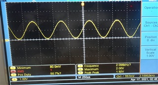
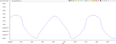
    Below are the waveforms of 2.1Khz on the scope as well as a graph (ADCBUF) in ccs 

    2.1KhzOriginal waveform2.1KHZAdcBUF

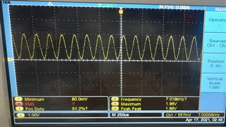
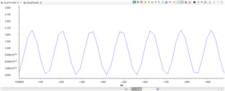
    The below waveform is for 7Khz 

    7Khz7Khzadcbuff

    The waveform for 2khz and 1 kHz are fine and correctly plots the graph in CCS. The issue can be seen for higher frequencies as well as decimal kind frequencies 

    I would emphasize I needed the correct data in ADCbuf for my FFT code so that I could get the frequency contents of the signal.

    Any suggestions regarding that would help.

    I hope this data helps.

    Regards,

    Nitesh M

  • Nitesh,

    Can you scroll down a bit on the ADC regs and also capture ADCTRL3?  Specifically I'm looking to see if ADCCLKPS is 3 or greater.  As it is now, The HSPCLK divider = 1(which divides the CPU clock by 2), which if ADCTRL3 = 0 would mean that the ADC is clocked at 75MHz.  The max clock for the ADC is 25MHz.

    If this does not solve the issue; can we try and increase the PWM sample rate and see if that addresses the issue?  Basically I'm looking to get more samples for the FFT to operate on.  If PWM is at 48kHz and you see issues with 7kHz input sine or above, we have 6 or less points per period.  If we can get the points back to where a 1kHz sine wave(48 points per period) it will improve the accuracy of the FFT.

    Best,

    Matthew