This thread has been locked.

If you have a related question, please click the "Ask a related question" button in the top right corner. The newly created question will be automatically linked to this question.

TMS320F28335: 【I2C】Temperature sensor value acquisition

Part Number: TMS320F28335
Other Parts Discussed in Thread: C2000WARE

I would like to use I2C to get the value of the temperature sensor.
The sensor used is "SparkFun (PID 14607) Grid-EYE Infrared Array".

I tried to configure the program by referring to the answers to the past questions, but the sensor value is not stored in the final rx_data_buff.

https://e2e.ti.com/support/microcontrollers/c2000/f/c2000-microcontrollers-forum/773846/ccs-launchxl-f28027-how-to-establish-i2c-communication-between-launchxl-f28027-and- mcp9808

When I run the current program, I get stuck in the loop at ARDY on line 292. Similarly, how to escape from RRDY on line 360 remains unknown.

// Included Files
#include "DSP2833x_Device.h"     // Device Headerfile and Examples Include File
#include "dsp2833x_i2c_defines.h"

extern void InitSysCtrl(void);
extern void InitPieCtrl(void);
extern void InitPieVectTable(void);

// I2C Function Prototypes
void   I2CA_Init(void);
void InitI2CAGpio();

unsigned short I2CA_WriteToReg(unsigned short slave_addr, unsigned short reg, unsigned short data[], unsigned short data_size);
unsigned short I2CA_WriteToManyRegs(unsigned short slave_addr, unsigned short reg[], unsigned short reg_size, unsigned short data[], unsigned short data_size);
unsigned short I2CA_ReadFromReg(unsigned short slave_addr, unsigned short reg, unsigned short data[], unsigned short data_size);
unsigned short I2CA_ReadFromManyRegs(unsigned short slave_addr, unsigned short reg[], unsigned short reg_size, unsigned short data[], unsigned short data_size);

// Defines
#define I2C_SLAVE_ADDR        0x50
#define NACK_CHECK            1

// Globals
    // I2C通信用定義
    unsigned short reg[2];              // Register bytes buffer
    unsigned short tx_data_buff[64];    // Data bytes buffer
    unsigned short rx_data_buff[64];    // Data bytes buffer

// Main
void main(void)
{
    unsigned short Status;
    unsigned short i;

    // レジスタバイト初期化
    reg[0] = 0x00;
    reg[1] = 0x00;

    // データバイト初期化
    for(i = 0; i <= sizeof(tx_data_buff); i++)
    {
        tx_data_buff[i] = i;
        rx_data_buff[i] = 0;
    }

    // WARNING: RAMから関数を実行する前に必ずmemcpyを呼び出すようにしてください。
    // InitSysCtrlにはRAMベースの関数の呼び出しが含まれており、最初にmemcpyを呼び出さないとプロセッサは「雑草の中」に入ります。
#ifdef _FLASH
    memcpy(&RamfuncsRunStart, &RamfuncsLoadStart, (size_t)&RamfuncsLoadSize);
#endif

    // システム制御の初期化:
    // PLL、WatchDog、ペリフェラルクロックを有効にする
    // このサンプル関数は、DSP2833x_SysCtrl.cファイルにあります。
    InitSysCtrl();
    
    // I2C機能のGPIOのみをセットアップする
    InitI2CAGpio();

    // すべての割り込みをクリアし、PIEベクトルテーブルを初期化します。
    DINT;

    // PIE制御レジスタをデフォルト状態に初期化します。
    // デフォルトの状態は、すべてのPIE割り込みが無効でフラグが設定されていることです。
    // この関数はDSP2833x_PieCtrl.cファイルにあります。
    InitPieCtrl();

    // CPU割り込みを無効にし、すべてのCPU割り込みフラグをクリアします
    IER = 0x0000;
    IFR = 0x0000;

    // シェル割り込みサービスルーチン(ISR)へのポインタを使用してPIEベクトルテーブルを初期化します。
    // この例で割り込みが使用されていない場合でも、これによりテーブル全体にデータが入力されます。 これはデバッグの目的で役立ちます。
    // シェルISRルーチンはDSP2833x_DefaultIsr.cにあります。
    // この関数はDSP2833x_PieVect.cにあります。
    InitPieVectTable();

    // すべてのデバイス周辺機器を初期化します
    I2CA_Init();    // I2C-A only

    // 転送レジスタとデータバイト
    Status = I2CA_WriteToManyRegs(I2C_SLAVE_ADDR, reg, sizeof(reg), tx_data_buff, sizeof(tx_data_buff));

    if(Status == I2C_SUCCESS)
    {
        Status = I2CA_ReadFromManyRegs(I2C_SLAVE_ADDR, reg, sizeof(reg), rx_data_buff, sizeof(rx_data_buff));
        while(Status != I2C_SUCCESS)
        {
            Status = I2CA_ReadFromManyRegs(I2C_SLAVE_ADDR, reg, sizeof(reg), rx_data_buff, sizeof(rx_data_buff));
        }
    }

    __asm("   ESTOP0");

}

// I2CA_Init -
void I2CA_Init(void)
{
    // I2CCLK = SYSCLK/(I2CPSC+1)
    // 10 = 150/(14+1)
#if CPU_FRQ_150MHZ
    I2caRegs.I2CPSC.all = 14;       // Prescaler - need 7-12 Mhz on module clk
#endif

#if CPU_FRQ_100MHZ
    I2caRegs.I2CPSC.all = 9;       // Prescaler - need 7-12 Mhz on module clk
#endif
    // Set I2CCLKL/I2CCLKH for 150KHz SCL clock
    I2caRegs.I2CCLKL = 10;           // NOTE: must be non zero
    I2caRegs.I2CCLKH = 5;            // NOTE: must be non zero
    I2caRegs.I2CIER.all = 0x0;      // enable interrupts(XRDY,RRDY,ARDY)

    // Take I2C out of reset. Stop I2C when suspended
    I2caRegs.I2CMDR.all = 0x0020;

    return;
}

// InitI2CGpio-この関数は、GPIOピンを初期化してI2Cピンとして機能させます
//
// 各GPIOピンはGPIOピンまたは最大3つの異なるものとして構成できます
// 周辺機能ピン。 デフォルトでは、すべてのピンがGPIOとして表示されます
// リセット後に入力します。
//
// 注意:
// SDAA操作に対して1つのGPIOピンのみを有効にする必要があります。
// SCLA操作に対して有効にするGPIOピンは1つだけです。
// 他の不要な行をコメントアウトします。
void
InitI2CAGpio()
{
    EALLOW;

    //選択したピンの内部プルアップを有効
    GpioCtrlRegs.GPBPUD.bit.GPIO32 = 0;   // Enable pull-up for GPIO32 (SDAA)
    GpioCtrlRegs.GPBPUD.bit.GPIO33 = 0;   // Enable pull-up for GPIO33 (SCLA)

    //選択したピンの修飾を非同期のみに設定
    GpioCtrlRegs.GPBQSEL1.bit.GPIO32 = 3;  // Asynch input GPIO32 (SDAA)
    GpioCtrlRegs.GPBQSEL1.bit.GPIO33 = 3;  // Asynch input GPIO33 (SCLA)

    // GPIOレジスタを使用してI2Cピンを構成
    GpioCtrlRegs.GPBMUX1.bit.GPIO32 = 1;   // Configure GPIO32 for SDAA
    GpioCtrlRegs.GPBMUX1.bit.GPIO33 = 1;   // Configure GPIO33 for SCLA

    EDIS;
}

// I2CA_WriteToReg-この関数はデータバイトをスレーブデバイスのレジスタに書き込みます。
//
// INPUTS:
//  --slave_addr ==>書き込まれるスレーブデバイスのアドレス
//  --reg [] ==>書き込み中のスレーブデバイスレジスタ
//  --reg_size ==>書き込まれるレジスタバイトの数、reg_sizeのバッファサイズ
//  --data [] ==>スレーブに書き込まれるバイトのデバイスレジスタデータバッファ
//  --data_size ==>書き込まれるデータバイトの数、データバッファのサイズ
unsigned short I2CA_WriteToManyRegs(unsigned short slave_addr, unsigned short reg[], unsigned short reg_size, unsigned short data[], unsigned short data_size)
{
    unsigned short i;
    unsigned short Status;

    Status = I2C_SUCCESS;

    // STPビットが以前のマスター通信からクリアされるまで待機します。
    // モジュールによるこのビットのクリアは、SCDビットが設定されるまで遅延されます。
    // 新しいメッセージを開始する前にこのビットがチェックされていないと、I2Cが混乱する可能性があります。
    if (I2caRegs.I2CMDR.bit.STP == 1)
    {
        return I2C_STP_NOT_READY_ERROR;
    }

    // Setup slave address
    I2caRegs.I2CSAR = slave_addr;

    // Check if bus busy
    if (I2caRegs.I2CSTR.bit.BB == 1)
    {
        return I2C_BUS_BUSY_ERROR;
    }

    // マスタートランスミッターとしてセットアップ
    // FREE + MST + TRX + IRS
    I2caRegs.I2CMDR.all = 0x4620;

    // 送信バイト数を設定
    // == (# of register bytes) + (# of data[] buffer bytes)
    I2caRegs.I2CCNT = reg_size + data_size;

    I2caRegs.I2CMDR.bit.STT = 0x1; // START条件を送信
    I2caRegs.I2CMDR.bit.STP = 0x1; // I2CCNTがゼロの場合、STOP条件が生成

    // I2Cモジュールは以下を送信:
    // register bytes ==> data bytes ==> STOP condition

    // レジスターバイトを送信
    while(!I2caRegs.I2CSTR.bit.XRDY){} // データを書き込む準備ができていることを確認

        #if NACK_CHECK // NACKを受信したかどうかを確認
            if(I2caRegs.I2CSTR.bit.NACK == 1)
            {
                I2caRegs.I2CMDR.bit.STP = 1;
                I2caRegs.I2CSTR.all = I2C_CLR_NACK_BIT;

                Status = I2C_ERROR;
                return Status;
            }
        #endif
    }

    // データバイトの送信とそれに続くSTOP条件
        while(!I2caRegs.I2CSTR.bit.XRDY){} // データを書き込む準備ができていることを確認

        #if NACK_CHECK // NACKを受信したかどうかを確認
            if(I2caRegs.I2CSTR.bit.NACK == 1)
            {
                I2caRegs.I2CMDR.bit.STP = 1;
                I2caRegs.I2CSTR.all = I2C_CLR_NACK_BIT;

                Status = I2C_ERROR;
                return Status;
            }
        #endif

    I2caRegs.I2CDXR = reg[0];
    I2caRegs.I2CDXR = reg[1];

    // Data successfully written
    return Status;
}

// I2CA_ReadFromManyRegs-この関数は、スレーブデバイスのレジスタからデータバイトを読み取ります。
// 初期書き込み時に複数のレジスタを送信する場合。
//
// INPUTS:
//  --slave_addr ==>読み取られているスレーブデバイスのアドレス
//  --reg [] ==>から読み取られるスレーブデバイスレジスタ
//  --reg_size ==>書き込まれるレジスタバイトの数、reg_sizeバッファのサイズ
//  --data [] ==>スレーブデバイスレジスタから読み取ったバイトを格納するデータバッファ
//  --data_size ==>受信するデータバイト数、データバッファのサイズ
unsigned short I2CA_ReadFromManyRegs(unsigned short slave_addr, unsigned short reg[], unsigned short reg_size, unsigned short data[], unsigned short data_size)
{
    unsigned short i;
    unsigned short Status;

    Status = I2C_SUCCESS;

    // STPビットが以前のマスター通信からクリアされるまで待機します
    // モジュールによるこのビットのクリアは、SCDビットが設定されるまで遅延されます。
    // 新しいメッセージを開始する前にこのビットがチェックされていないと、I2Cが混乱する可能性があります。
    if (I2caRegs.I2CMDR.bit.STP == 1)
    {
        return I2C_STP_NOT_READY_ERROR;
    }

    // スレーブアドレスの設定
    I2caRegs.I2CSAR = slave_addr;

    // Check if bus busy
    if (I2caRegs.I2CSTR.bit.BB == 1)
    {
        return I2C_BUS_BUSY_ERROR;
    }

    // 1. スレーブアドレスを送信し、続いてレジスタバイトを送信します。

    // 送信するバイト数を設定
    // == # of register bytes
    I2caRegs.I2CCNT = reg_size;

    // マスター送信機として設定
    // FREE + MST + TRX + IRS
    I2caRegs.I2CMDR.all = 0x4620;

    I2caRegs.I2CMDR.bit.STT = 0x1; // START条件を送信

    while(!I2caRegs.I2CSTR.bit.ARDY) // スレーブアドレスが送信されるまで待機
    {
        if(I2caRegs.I2CSTR.bit.XSMT == 0)
        {
            break; // スレーブアドレスでACKを受信
        }
    }

    #if NACK_CHECK // NACKを受信したかどうかを確認
        if(I2caRegs.I2CSTR.bit.NACK == 1)
        {
            I2caRegs.I2CMDR.bit.STP = 1;
            I2caRegs.I2CSTR.all = I2C_CLR_NACK_BIT;

            Status = I2C_ERROR;
            return Status;
        }
    #endif


    // レジスタバイトの送信
    for (i=0; i< reg_size; i++)
    {
        while(!I2caRegs.I2CSTR.bit.XRDY){} // データを書き込む準備ができていることを確認
        I2caRegs.I2CDXR = reg[i];

        #if NACK_CHECK // NACKを受信したかどうかを確認
            if(I2caRegs.I2CSTR.bit.NACK == 1)
            {
                I2caRegs.I2CMDR.bit.STP = 1;
                I2caRegs.I2CSTR.all = I2C_CLR_NACK_BIT;

                Status = I2C_ERROR;
                return Status;
            }
        #endif
    }

    // 前の通信が完了するのを待つ
    while(!I2caRegs.I2CSTR.bit.ARDY){}

    // 2. スレーブデバイスからデータバイトを受信する

    // マスターレシーバーとして設定
    // FREE + MST + IRS ==> (Master Receiver)
    I2caRegs.I2CMDR.all = 0x4420;

    // 受信するバイト数を設定
    // == # of data bytes
    I2caRegs.I2CCNT = data_size;

    I2caRegs.I2CMDR.bit.STT = 0x1; // I2CCNTがゼロのときに生成されるSTART条件とスレーブアドレスセットのSTOP条件を繰り返し送信
    I2caRegs.I2CMDR.bit.STP = 0x1;

    #if NACK_CHECK // NACKを受信したかどうかを確認
        if(I2caRegs.I2CSTR.bit.NACK == 1)
        {
            I2caRegs.I2CMDR.bit.STP = 1;
            I2caRegs.I2CSTR.all = I2C_CLR_NACK_BIT;

            Status = I2C_ERROR;
            return Status;
        }
    #endif

    for (i=0; i< data_size; i++)
    {
        while(!I2caRegs.I2CSTR.bit.RRDY){} // データを受信する準備ができていることを確認
        data[i] = I2caRegs.I2CDRR; // 受信したバイトをバッファリング
    }

    // Data successfully read
    return Status;
}

// End of File


We would appreciate it if you could suggest sample code.
Thank you.

  • Hi,

    We released some improved I2C examples in the latest C2000WARE. I'd recommend you take a loot at them and leverage the i2cLib files for your project.

    C:\ti\c2000\C2000Ware_3_04_00_00\device_support\f2806x\examples\c28\i2c_Lib_eeprom_polling

    C:\ti\c2000\C2000Ware_3_04_00_00\device_support\f2806x\examples\c28\i2c_Lib_eeprom_interrupt

    Note that the SW examples are written for the F2806x device, but they can be used for the F2833x device as well. The line below in the .h can be changed to 16 for your device.

    #define I2C_FIFO_LEVEL              16

    Best,

    Kevin

  • Thank you for your reply.
    Where can I get the latest C2000WARE that taught me?

  • Hi,

    You can download the latest version 3.04.00.00 it from here: https://www.ti.com/tool/C2000WARE#downloads

    I recommend installing it in the default directory (C:\ti).

    Best,

    Kevin

  • hi, Kevin

    The latest C2000WARE has been downloaded.
    The sample you suggested was for the F2806x device, but the sample for the device you are using (F2833x) was in the hierarchy below, so I decided to use it.

    C: \ ti \ c2000 \ C2000Ware_3_04_00_00 \ device_support \ f2833x \ examples \ i2c_eeprom

    However, there is a problem.
    Since "I2cMsgOut1.MsgStatus" remains "I2C_MSGSTAT_INACTIVE", the condition on line 251 of the source code is not satisfied and it is not possible to move to the write section.

    I will attach the source code, so please let me know if there are any changes.

    //###########################################################################
    //
    // FILE:	Example_2833xI2C_eeprom.c
    //
    // TITLE:	I2C EEPROM Example
    //
    //! \addtogroup f2833x_example_list
    //! <h1>I2C EEPROM (i2c_eeprom)</h1>
    //!
    //!  This program requires an external I2C EEPROM connected to
    //!  the I2C bus at address 0x50. \n
    //!  This program will write 1-14 words to EEPROM and read them back.
    //!  The data written and the EEPROM address written to are contained
    //!  in the message structure, \b I2cMsgOut1. The data read back will be
    //!  contained in the message structure \b I2cMsgIn1.
    //!
    //!  \b Watch \b Variables \n
    //!  - I2cMsgIn1
    //!  - I2cMsgOut1
    //
    //###########################################################################
    // $TI Release: F2833x Support Library v2.02.00.00 $
    // $Release Date: Fri Feb 12 19:15:21 IST 2021 $
    // $Copyright:
    // Copyright (C) 2009-2021 Texas Instruments Incorporated - http://www.ti.com/
    //
    // Redistribution and use in source and binary forms, with or without 
    // modification, are permitted provided that the following conditions 
    // are met:
    // 
    //   Redistributions of source code must retain the above copyright 
    //   notice, this list of conditions and the following disclaimer.
    // 
    //   Redistributions in binary form must reproduce the above copyright
    //   notice, this list of conditions and the following disclaimer in the 
    //   documentation and/or other materials provided with the   
    //   distribution.
    // 
    //   Neither the name of Texas Instruments Incorporated nor the names of
    //   its contributors may be used to endorse or promote products derived
    //   from this software without specific prior written permission.
    // 
    // THIS SOFTWARE IS PROVIDED BY THE COPYRIGHT HOLDERS AND CONTRIBUTORS 
    // "AS IS" AND ANY EXPRESS OR IMPLIED WARRANTIES, INCLUDING, BUT NOT 
    // LIMITED TO, THE IMPLIED WARRANTIES OF MERCHANTABILITY AND FITNESS FOR
    // A PARTICULAR PURPOSE ARE DISCLAIMED. IN NO EVENT SHALL THE COPYRIGHT 
    // OWNER OR CONTRIBUTORS BE LIABLE FOR ANY DIRECT, INDIRECT, INCIDENTAL, 
    // SPECIAL, EXEMPLARY, OR CONSEQUENTIAL DAMAGES (INCLUDING, BUT NOT 
    // LIMITED TO, PROCUREMENT OF SUBSTITUTE GOODS OR SERVICES; LOSS OF USE,
    // DATA, OR PROFITS; OR BUSINESS INTERRUPTION) HOWEVER CAUSED AND ON ANY
    // THEORY OF LIABILITY, WHETHER IN CONTRACT, STRICT LIABILITY, OR TORT 
    // (INCLUDING NEGLIGENCE OR OTHERWISE) ARISING IN ANY WAY OUT OF THE USE 
    // OF THIS SOFTWARE, EVEN IF ADVISED OF THE POSSIBILITY OF SUCH DAMAGE.
    // $
    //###########################################################################
    
    //
    // Included Files
    //
    #include "DSP28x_Project.h"     // Device Headerfile and Examples Include File
    
    //
    // Note: I2C Macros used in this example can be found in the
    // DSP2833x_I2C_defines.h file
    //
    
    //
    // Function Prototypes
    //
    void   I2CA_Init(void);
    Uint16 I2CA_WriteData(struct I2CMSG *msg);
    Uint16 I2CA_ReadData(struct I2CMSG *msg);
    __interrupt void i2c_int1a_isr(void);
    void pass(void);
    void fail(void);
    
    //
    // Defines
    //
    #define I2C_SLAVE_ADDR        0x50
    #define I2C_NUMBYTES          4
    #define I2C_EEPROM_HIGH_ADDR  0x00
    #define I2C_EEPROM_LOW_ADDR   0x30
    
    //
    // Globals
    //
    
    //
    // Two bytes will be used for the outgoing address, thus only setup 14 bytes 
    // maximum
    //
    struct I2CMSG I2cMsgOut1=
    {
        I2C_MSGSTAT_SEND_WITHSTOP,
        I2C_SLAVE_ADDR,
        I2C_NUMBYTES,
        I2C_EEPROM_HIGH_ADDR,
        I2C_EEPROM_LOW_ADDR,
        0x12,                   // Msg Byte 1
        0x34,                   // Msg Byte 2
        0x56,                   // Msg Byte 3
        0x78,                   // Msg Byte 4
        0x9A,                   // Msg Byte 5
        0xBC,                   // Msg Byte 6
        0xDE,                   // Msg Byte 7
        0xF0,                   // Msg Byte 8
        0x11,                   // Msg Byte 9
        0x10,                   // Msg Byte 10
        0x11,                   // Msg Byte 11
        0x12,                   // Msg Byte 12
        0x13,                   // Msg Byte 13
        0x12                    // Msg Byte 14
    };
    
    struct I2CMSG I2cMsgIn1=
    {   I2C_MSGSTAT_SEND_NOSTOP,
        I2C_SLAVE_ADDR,
        I2C_NUMBYTES,
        I2C_EEPROM_HIGH_ADDR,
        I2C_EEPROM_LOW_ADDR
    };
    
    //
    // Globals
    //
    struct I2CMSG *CurrentMsgPtr;				// Used in interrupts
    Uint16 PassCount;
    Uint16 FailCount;
    
    //
    // Main
    //
    void main(void)
    {
        Uint16 Error;
        Uint16 i;
    
        CurrentMsgPtr = &I2cMsgOut1;
    
        //
        // Step 1. Initialize System Control:
        // PLL, WatchDog, enable Peripheral Clocks
        // This example function is found in the DSP2833x_SysCtrl.c file.
        //
        InitSysCtrl();
    
        //
        // Step 2. Initialize GPIO:
        // This example function is found in the DSP2833x_Gpio.c file and
        // illustrates how to set the GPIO to it's default state.
        //
        // InitGpio();
        
        //
        // Setup only the GP I/O only for I2C functionality
        //
        InitI2CGpio();
    
        //
        // Step 3. Clear all interrupts and initialize PIE vector table
        // Disable CPU interrupts
        //
        DINT;
    
        //
        // Initialize PIE control registers to their default state.
        // The default state is all PIE interrupts disabled and flags
        // are cleared.
        // This function is found in the DSP2833x_PieCtrl.c file.
        //
        InitPieCtrl();
    
        //
        // Disable CPU interrupts and clear all CPU interrupt flags
        //
        IER = 0x0000;
        IFR = 0x0000;
    
        //
        // Initialize the PIE vector table with pointers to the shell Interrupt
        // Service Routines (ISR).
        // This will populate the entire table, even if the interrupt
        // is not used in this example.  This is useful for debug purposes.
        // The shell ISR routines are found in DSP2833x_DefaultIsr.c.
        // This function is found in DSP2833x_PieVect.c.
        //
        InitPieVectTable();
    
        //
        // Interrupts that are used in this example are re-mapped to
        // ISR functions found within this file.
        //
        EALLOW;	    // This is needed to write to EALLOW protected registers
        PieVectTable.I2CINT1A = &i2c_int1a_isr;
        EDIS;   // This is needed to disable write to EALLOW protected registers
    
        //
        // Step 4. Initialize all the Device Peripherals:
        // This function is found in DSP2833x_InitPeripherals.c
        //
        // InitPeripherals(); // Not required for this example
        I2CA_Init();
    
        //
        // Step 5. User specific code
        //
    
        //
        // Clear Counters
        //
        PassCount = 0;
        FailCount = 0;
    
        //
        // Clear incoming message buffer
        //
        for (i = 0; i < I2C_MAX_BUFFER_SIZE; i++)
        {
            I2cMsgIn1.MsgBuffer[i] = 0x0000;
        }
    
        //
        // Enable interrupts required for this example
        //
    
        //
        // Enable I2C interrupt 1 in the PIE: Group 8 interrupt 1
        //
        PieCtrlRegs.PIEIER8.bit.INTx1 = 1;
    
        //
        // Enable CPU INT8 which is connected to PIE group 8
        //
        IER |= M_INT8;
        EINT;
    
        //
        // Application loop
        //
        for(;;)
        {
            //
            // Write data to EEPROM section
            //
    
            //
            // Check the outgoing message to see if it should be sent.
            // In this example it is initialized to send with a stop bit.
            //
            if(I2cMsgOut1.MsgStatus == I2C_MSGSTAT_SEND_WITHSTOP)
            {
                Error = I2CA_WriteData(&I2cMsgOut1);
                
                //
                // If communication is correctly initiated, set msg status to busy
                // and update CurrentMsgPtr for the interrupt service routine.
                // Otherwise, do nothing and try again next loop. Once message is
                // initiated, the I2C interrupts will handle the rest. Search for
                // ICINTR1A_ISR in the i2c_eeprom_isr.c file.
                //
                if (Error == I2C_SUCCESS)
                {
                    CurrentMsgPtr = &I2cMsgOut1;
                    I2cMsgOut1.MsgStatus = I2C_MSGSTAT_WRITE_BUSY;
                }
            }  // end of write section
    
            //
            // Read data from EEPROM section
            //
    
            //
            // Check outgoing message status. Bypass read section if status is
            // not inactive.
            //
            if (I2cMsgOut1.MsgStatus == I2C_MSGSTAT_INACTIVE)
            {
                //
                // Check incoming message status.
                //
                if(I2cMsgIn1.MsgStatus == I2C_MSGSTAT_SEND_NOSTOP)
                {
                    //
                    // EEPROM address setup portion
                    //
                    while(I2CA_ReadData(&I2cMsgIn1) != I2C_SUCCESS)
                    {
                        //
                        // Maybe setup an attempt counter to break an infinite 
                        // while loop. The EEPROM will send back a NACK while it is 
                        // performing a write operation. Even though the write 
                        // communique is complete at this point, the EEPROM could 
                        // still be busy programming the data. Therefore, multiple 
                        // attempts are necessary.
                        //
                    }
                    
                    //
                    // Update current message pointer and message status
                    //
                    CurrentMsgPtr = &I2cMsgIn1;
                    I2cMsgIn1.MsgStatus = I2C_MSGSTAT_SEND_NOSTOP_BUSY;
                }
    
                //
                // Once message has progressed past setting up the internal address
                // of the EEPROM, send a restart to read the data bytes from the
                // EEPROM. Complete the communique with a stop bit. MsgStatus is
                // updated in the interrupt service routine.
                //
                else if(I2cMsgIn1.MsgStatus == I2C_MSGSTAT_RESTART)
                {
                    //
                    // Read data portion
                    //
                    while(I2CA_ReadData(&I2cMsgIn1) != I2C_SUCCESS)
                    {
                        //
                        // Maybe setup an attempt counter to break an infinite 
                        // while loop.
                        //
                    }
                    
                    //
                    // Update current message pointer and message status
                    //
                    CurrentMsgPtr = &I2cMsgIn1;
                    I2cMsgIn1.MsgStatus = I2C_MSGSTAT_READ_BUSY;
                }
            }  // end of read section
        }   // end of for(;;)
    }   // end of main
    
    //
    // I2CA_Init -
    //
    void 
    I2CA_Init(void)
    {
        //
        // Initialize I2C
        //
        I2caRegs.I2CSAR = 0x0050;	// Slave address - EEPROM control code
    
    #if (CPU_FRQ_150MHZ)            // Default - For 150MHz SYSCLKOUT
        //
        // Prescaler - need 7-12 Mhz on module clk (150/15 = 10MHz)
        //
        I2caRegs.I2CPSC.all = 14;
    #endif
    #if (CPU_FRQ_100MHZ)            // For 100 MHz SYSCLKOUT
        //
        // Prescaler - need 7-12 Mhz on module clk (100/10 = 10MHz)
        //    
        I2caRegs.I2CPSC.all = 9;
    #endif
    
        I2caRegs.I2CCLKL = 10;		// NOTE: must be non zero
        I2caRegs.I2CCLKH = 5;		// NOTE: must be non zero
        I2caRegs.I2CIER.all = 0x24;	// Enable SCD & ARDY interrupts
    
        //
        // Take I2C out of reset
        // Stop I2C when suspended
        //
        I2caRegs.I2CMDR.all = 0x0020;	
    
        I2caRegs.I2CFFTX.all = 0x6000;	// Enable FIFO mode and TXFIFO
        I2caRegs.I2CFFRX.all = 0x2040;	// Enable RXFIFO, clear RXFFINT,
    
        return;
    }
    
    //
    // I2CA_WriteData -
    //
    Uint16 
    I2CA_WriteData(struct I2CMSG *msg)
    {
        Uint16 i;
    
        //
        // Wait until the STP bit is cleared from any previous master communication
        // Clearing of this bit by the module is delayed until after the SCD bit is
        // set. If this bit is not checked prior to initiating a new message, the
        // I2C could get confused.
        //
        if (I2caRegs.I2CMDR.bit.STP == 1)
        {
            return I2C_STP_NOT_READY_ERROR;
        }
    
        //
        // Setup slave address
        //
        I2caRegs.I2CSAR = msg->SlaveAddress;
    
        //
        // Check if bus busy
        //
        if (I2caRegs.I2CSTR.bit.BB == 1)
        {
            return I2C_BUS_BUSY_ERROR;
        }
    
        //
        // Setup number of bytes to send MsgBuffer + Address
        //
        I2caRegs.I2CCNT = msg->NumOfBytes+2;
    
        //
        // Setup data to send
        //
        I2caRegs.I2CDXR = msg->MemoryHighAddr;
        I2caRegs.I2CDXR = msg->MemoryLowAddr;
    
        for (i=0; i<msg->NumOfBytes; i++)
        {
            I2caRegs.I2CDXR = *(msg->MsgBuffer+i);
        }
    
        //
        // Send start as master transmitter
        //
        I2caRegs.I2CMDR.all = 0x6E20;
    
        return I2C_SUCCESS;
    }
    
    //
    // I2CA_ReadData - 
    //
    Uint16 
    I2CA_ReadData(struct I2CMSG *msg)
    {
        //
        // Wait until the STP bit is cleared from any previous master communication.
        // Clearing of this bit by the module is delayed until after the SCD bit is
        // set. If this bit is not checked prior to initiating a new message, the
        // I2C could get confused.
        //
        if (I2caRegs.I2CMDR.bit.STP == 1)
        {
            return I2C_STP_NOT_READY_ERROR;
        }
    
        I2caRegs.I2CSAR = msg->SlaveAddress;
    
        if(msg->MsgStatus == I2C_MSGSTAT_SEND_NOSTOP)
        {
            //
            // Check if bus busy
            //
            if (I2caRegs.I2CSTR.bit.BB == 1)
            {
                return I2C_BUS_BUSY_ERROR;
            }
            I2caRegs.I2CCNT = 2;
            I2caRegs.I2CDXR = msg->MemoryHighAddr;
            I2caRegs.I2CDXR = msg->MemoryLowAddr;
            I2caRegs.I2CMDR.all = 0x2620;	// Send data to setup EEPROM address
        }
        else if(msg->MsgStatus == I2C_MSGSTAT_RESTART)
        {
            I2caRegs.I2CCNT = msg->NumOfBytes;	// Setup how many bytes to expect
            I2caRegs.I2CMDR.all = 0x2C20;		// Send restart as master receiver
        }
    
        return I2C_SUCCESS;
    }
    
    //
    // i2c_int1a_isr - I2C-A
    //
    __interrupt void
    i2c_int1a_isr(void)
    {
        Uint16 IntSource, i;
    
        //
        // Read interrupt source
        //
        IntSource = I2caRegs.I2CISRC.all;
    
        //
        // Interrupt source = stop condition detected
        //
        if(IntSource == I2C_SCD_ISRC)
        {
            //
            // If completed message was writing data, reset msg to inactive state
            //
            if (CurrentMsgPtr->MsgStatus == I2C_MSGSTAT_WRITE_BUSY)
            {
                CurrentMsgPtr->MsgStatus = I2C_MSGSTAT_INACTIVE;
            }
            else
            {
                //
                // If a message receives a NACK during the address setup portion 
                // of the EEPROM read, the code further below included in the 
                // register access ready interrupt source code will generate a stop
                // condition. After the stop condition is received (here), set the 
                // message status to try again. User may want to limit the number 
                // of retries before generating an error.
                //
                if(CurrentMsgPtr->MsgStatus == I2C_MSGSTAT_SEND_NOSTOP_BUSY)
                {
                    CurrentMsgPtr->MsgStatus = I2C_MSGSTAT_SEND_NOSTOP;
                }
                
                //
                // If completed message was reading EEPROM data, reset msg 
                // to inactive state and read data from FIFO.
                //
                else if (CurrentMsgPtr->MsgStatus == I2C_MSGSTAT_READ_BUSY)
                {
                    CurrentMsgPtr->MsgStatus = I2C_MSGSTAT_INACTIVE;
                    for(i=0; i < I2C_NUMBYTES; i++)
                    {
                        CurrentMsgPtr->MsgBuffer[i] = I2caRegs.I2CDRR;
                    }
                    {
                        //
                        // Check received data
                        //
                        for(i=0; i < I2C_NUMBYTES; i++)
                        {
                            if(I2cMsgIn1.MsgBuffer[i] == I2cMsgOut1.MsgBuffer[i])
                            {
                                PassCount++;
                            }
                            else
                            {
                                FailCount++;
                            }
                        }
                        
                        if(PassCount == I2C_NUMBYTES)
                        {
                            pass();
                        }
                        else
                        {
                            fail();
                        }
                    }
                }
            }
        }  // end of stop condition detected
    
        //
        // Interrupt source = Register Access Ready
        // This interrupt is used to determine when the EEPROM address setup 
        // portion of the read data communication is complete. Since no stop bit is
        // commanded, this flag tells us when the message has been sent instead of 
        // the SCD flag. If a NACK is received, clear the NACK bit and command a 
        // stop. Otherwise, move on to the read data portion of the communication.
        //
        else if(IntSource == I2C_ARDY_ISRC)
        {
            if(I2caRegs.I2CSTR.bit.NACK == 1)
            {
                I2caRegs.I2CMDR.bit.STP = 1;
                I2caRegs.I2CSTR.all = I2C_CLR_NACK_BIT;
            }
            else if(CurrentMsgPtr->MsgStatus == I2C_MSGSTAT_SEND_NOSTOP_BUSY)
            {
                CurrentMsgPtr->MsgStatus = I2C_MSGSTAT_RESTART;
            }
        }
    
        else
        {
            //
            // Generate some error due to invalid interrupt source
            //
            __asm("   ESTOP0");
        }
    
        //
        // Enable future I2C (PIE Group 8) interrupts
        //
        PieCtrlRegs.PIEACK.all = PIEACK_GROUP8;
    }
    
    //
    // pass - 
    //
    void pass()
    {
        __asm("   ESTOP0");
        for(;;);
    }
    
    //
    // fail -
    //
    void fail()
    {
        __asm("   ESTOP0");
        for(;;);
    }
    
    //
    // End of File
    //


  • When I tried to execute it again, I was able to transition from "I2C_MSGSTAT_INACTIVE".
    However, the condition on line 389 was met and the Write section was looped by "I2C_STP_NOT_READY_ERROR;".

    Please tell me the solution.
    The source code has not changed from the one attached earlier.

  • Hi,

    The i2c_eeprom example for the F2833x you're referencing is designed for an I2C EEPROM. It is not easy to comprehend the state machine utilized and it is difficult to leverage for devices other than an eeprom. I would not recommend using this example for reading from your temp sensor.

    I recommend you look at the F2806x device examples I mentioned and utilize the i2cLib_FIFO.c and .h source files within them. The functions will work for the F2833x just as good and they are simpler to use for interfacing with any i2c device.

    Best,

    Kevin

  • hi, Kevin

    When I run the F2806x sample, it gets stuck in the function "fail ()".
    Please let me know if there are any points that should be changed.

  • Hi,

    You will have to tailor the code to your specific I2C device, it will not send the correct commands and meet the protocol for your temp sensor by default.You will need to reference your I2C sensor's datasheet and use the functions in the i2cLib_FIFO.c and .h source files to send and receive the correct commands/data.

    Best,

    Kevin

  • I think there is no problem with the settings of i2cLib_FIFO_polling.c. However, I am not confident about microcomputers because I am a beginner. I will attach the source, so please let me know if there are any mistakes.

    //###########################################################################
    //
    // FILE:   i2cLib_FIFO_polling.c
    //
    // TITLE:  I2C FIFO Polling Library source file.
    //
    //###########################################################################
    // $TI Release: F2806x Support Library v2.06.00.00 $
    // $Release Date: Fri Feb 12 19:15:11 IST 2021 $
    // $Copyright:
    // Copyright (C) 2009-2021 Texas Instruments Incorporated - http://www.ti.com/
    //
    // Redistribution and use in source and binary forms, with or without 
    // modification, are permitted provided that the following conditions 
    // are met:
    // 
    //   Redistributions of source code must retain the above copyright 
    //   notice, this list of conditions and the following disclaimer.
    // 
    //   Redistributions in binary form must reproduce the above copyright
    //   notice, this list of conditions and the following disclaimer in the 
    //   documentation and/or other materials provided with the   
    //   distribution.
    // 
    //   Neither the name of Texas Instruments Incorporated nor the names of
    //   its contributors may be used to endorse or promote products derived
    //   from this software without specific prior written permission.
    // 
    // THIS SOFTWARE IS PROVIDED BY THE COPYRIGHT HOLDERS AND CONTRIBUTORS 
    // "AS IS" AND ANY EXPRESS OR IMPLIED WARRANTIES, INCLUDING, BUT NOT 
    // LIMITED TO, THE IMPLIED WARRANTIES OF MERCHANTABILITY AND FITNESS FOR
    // A PARTICULAR PURPOSE ARE DISCLAIMED. IN NO EVENT SHALL THE COPYRIGHT 
    // OWNER OR CONTRIBUTORS BE LIABLE FOR ANY DIRECT, INDIRECT, INCIDENTAL, 
    // SPECIAL, EXEMPLARY, OR CONSEQUENTIAL DAMAGES (INCLUDING, BUT NOT 
    // LIMITED TO, PROCUREMENT OF SUBSTITUTE GOODS OR SERVICES; LOSS OF USE,
    // DATA, OR PROFITS; OR BUSINESS INTERRUPTION) HOWEVER CAUSED AND ON ANY
    // THEORY OF LIABILITY, WHETHER IN CONTRACT, STRICT LIABILITY, OR TORT 
    // (INCLUDING NEGLIGENCE OR OTHERWISE) ARISING IN ANY WAY OUT OF THE USE 
    // OF THIS SOFTWARE, EVEN IF ADVISED OF THE POSSIBILITY OF SUCH DAMAGE.
    // $
    //###########################################################################
    
    #include "i2cLib_FIFO_polling.h"
    #include "DSP28x_Project.h"
    
    //
    // Global variables used by i2cLib_FIFO_polling
    //
    Uint16 timeoutCheck;
    
    //
    // I2C_TxSlaveAddress_ControlBytes - This function transmits the SlaveAddr
    //      and pControlBuffer control bytes of the passed I2CHandle.
    //
    Uint16 I2C_TxSlaveAddress_ControlBytes(struct I2CHandle *I2C_Params)
    {
        Uint16 status;
    
        //
        // Check if the I2C bus is busy before starting comms
        //
        status = checkBusStatus();
    
        if(status)
        {
            return status;
        }
    
        //
        // Set up as master transmitter
        // FREE + MST + TRX + IRS
        //
        I2caRegs.I2CMDR.all = 0x4620;
    
        //
        // Setup slave address
        //
        I2caRegs.I2CSAR = I2C_Params->SlaveAddr;
    
        I2caRegs.I2CMDR.bit.STT = 0x1; // Send START condition
    
        Uint16 count;
    
        //
        // Transmit NumOfControlBytes that are in pControlBuffer
        //
        for(count=0;count<I2C_Params->NumOfControlBytes;count++)
        {
            // Write control byte to I2C transmit FIFO
            I2caRegs.I2CDXR = I2C_Params->pControlBuffer[count];
    
            timeoutCheck = I2C_Params->Timeout;
    
            //
            // Wait for data to be transmitted out of FIFO.
            // Times out if TX takes too long.
            //
            while(I2caRegs.I2CFFTX.bit.TXFFST)
            {
                status = handleNACKandTimeout();
    
                if(status)
                {
                    return status;
                }
    
                DELAY_US(10);
            }
        }
    
        return SUCCESS;
    }
    
    //
    // I2C_MasterWrite - This function transmits the full I2C message of the
    //      passed I2CHandle. Function sequence is the following:
    //
    //      1. Generate START condition and transmit SlaveAddr
    //      2. Transmit NumOfControlBytes in pControlBuffer
    //      3. Transmit NumOfDataBytes in pMsgBuffer
    //      4. Generate STOP condition
    //
    Uint16 I2C_MasterWrite(struct I2CHandle *I2C_Params)
    {
        Uint16 status, buff_pos = 0;
    
        if(I2C_Params->NumOfDataBytes > MAX_BUFFER_SIZE)
        {
            return ERROR_BUFFER_MAX;
        }
    
        // Enable TX FIFO
        I2caRegs.I2CFFTX.all = 0x6000;
    
        // Set I2CCNT to number of bytes to transmit
        I2caRegs.I2CCNT = (I2C_Params->NumOfControlBytes) +
                (I2C_Params->NumOfDataBytes);
    
        //
        // Transmit slave address and control bytes
        //
        status = I2C_TxSlaveAddress_ControlBytes(I2C_Params);
    
        if(status)
        {
            return status;
        }
    
        //
        // Calculate number of bytes to be transmitted out of the FIFO
        //
        Uint16 numofFourBytes  = (I2C_Params->NumOfDataBytes) / I2C_FIFO_LEVEL;
        Uint16 remainingBytes    = (I2C_Params->NumOfDataBytes) % I2C_FIFO_LEVEL;
    
        Uint16 i,count = 0;
    
        //
        // Transmit bytes in pMsgBuffer using the full I2C_FIFO_LEVEL
        //
        while(count < numofFourBytes)
        {
            //
            // Fill the TX FIFO up to I2C_FIFO_LEVEL
            //
            for(i=1;i<=I2C_FIFO_LEVEL;i++)
            {
                I2caRegs.I2CDXR = I2C_Params->pMsgBuffer[buff_pos++];
            }
    
            timeoutCheck = I2C_Params->Timeout;
    
            //
            // Wait for data to be transmitted out of FIFO.
            // Times out if TX takes too long.
            //
            while(I2caRegs.I2CFFTX.bit.TXFFST)
            {
                status = handleNACKandTimeout();
    
                if(status)
                {
                    return status;
                }
    
                DELAY_US(10);
            }
    
            count++;
        }
    
        //
        // Fill the TX FIFO up to remainingBytes
        //
        for (i=0; i < remainingBytes; i++)
        {
            I2caRegs.I2CDXR = I2C_Params->pMsgBuffer[buff_pos++];
        }
    
        timeoutCheck = I2C_Params->Timeout;
    
        //
        // Wait for data to be transmitted out of FIFO.
        // Times out if TX takes too long.
        //
        while(I2caRegs.I2CFFTX.bit.TXFFST)
        {
            status = handleNACKandTimeout();
    
            if(status)
            {
                return status;
            }
    
            DELAY_US(10);
        }
    
        // Generate STOP condition
        I2caRegs.I2CMDR.bit.STP = 1;
    
        timeoutCheck = I2C_Params->Timeout;
    
        //
        // Wait for STOP condition to be generated.
        // Times out if STOP condition not generated in time.
        //
        while(I2caRegs.I2CMDR.bit.STP)
        {
            status = handleNACKandTimeout();
    
            if(status)
            {
                return status;
            }
    
            DELAY_US(10);
        }
    
        return SUCCESS;
    }
    
    //
    // I2C_MasterRead - This function reads data bytes from an I2C slave device
    //      based on the passed I2CHandle. Function sequence is the following:
    //
    //      1. Generate START condition and transmit SlaveAddr
    //      2. Transmit NumOfControlBytes in pControlBuffer
    //      3. Generate repeated START condition
    //      4. Receive NumOfDataBytes into pMsgBuffer
    //      5. Generate STOP condition
    //
    Uint16 I2C_MasterRead(struct I2CHandle *I2C_Params)
    {
        Uint16 status, buff_pos = 0;
    
        if(I2C_Params->NumOfDataBytes > MAX_BUFFER_SIZE)
        {
            return ERROR_BUFFER_MAX;
        }
    
        // Enable TX FIFO
        I2caRegs.I2CFFTX.all = 0x6000;
    
        // Set I2CCNT for number of control bytes to transmit
        I2caRegs.I2CCNT = I2C_Params->NumOfControlBytes;
    
        //
        // Transmit slave address and control bytes
        //
        status = I2C_TxSlaveAddress_ControlBytes(I2C_Params);
    
        // Disable TX FIFO
        I2caRegs.I2CFFTX.bit.TXFFRST = 0;
    
        if(status)
        {
            return status;
        }
    
        //
        // Calculate number of bytes to be received into the FIFO
        //
        Uint16 numofFourBytes  = (I2C_Params->NumOfDataBytes) / I2C_FIFO_LEVEL;
        Uint16 remainingBytes    = (I2C_Params->NumOfDataBytes) % I2C_FIFO_LEVEL;
    
        // Set I2CCNT for number of bytes to receive
        I2caRegs.I2CCNT = I2C_Params->NumOfDataBytes;
    
        // Enable RX FIFO
        I2caRegs.I2CFFRX.all = 0x2040;
    
        //
        // Set up as master receiver
        // FREE + MST + IRS
        //
        I2caRegs.I2CMDR.all = 0x4420;
    
        I2caRegs.I2CMDR.bit.STT = 0x1; // Send repeated START condition
    
        Uint16 i,count = 0;
    
        //
        // Receive bytes into pMsgBuffer using the full I2C_FIFO_LEVEL
        //
        while(count < numofFourBytes)
        {
            timeoutCheck = I2C_Params->Timeout;
    
            //
            // Wait for data to be received into FIFO.
            // Times out if RX takes too long.
            //
            while(!(I2caRegs.I2CFFRX.bit.RXFFST == I2C_FIFO_LEVEL))
            {
                status = handleNACKandTimeout();
    
                if(status)
                {
                    return status;
                }
    
                DELAY_US(10);
            }
    
            //
            // Read all bytes currently in FIFO
            //
            for(i=0; i<I2C_FIFO_LEVEL; i++)
            {
                I2C_Params->pMsgBuffer[buff_pos++] = I2caRegs.I2CDRR;
            }
    
            count++;
        }
    
        //
        // Receive remainingBytes if there are any.
        //
        if(remainingBytes)
        {
            timeoutCheck = I2C_Params->Timeout;
    
            //
            // Wait for remainingBytes to be received into FIFO.
            // Times out if RX takes too long.
            //
            while(!(I2caRegs.I2CFFRX.bit.RXFFST == remainingBytes))
            {
                status = handleNACKandTimeout();
    
                if(status)
                {
                    return status;
                }
    
                DELAY_US(10);
            }
    
            //
            // Read remainingBytes currently in FIFO
            //
            for(i=0; i<remainingBytes; i++)
            {
                I2C_Params->pMsgBuffer[buff_pos++] = I2caRegs.I2CDRR;
            }
        }
    
        //
        // Generate STOP condition
        //
        I2caRegs.I2CMDR.bit.STP = 1;
    
        timeoutCheck = I2C_Params->Timeout;
    
        //
        // Wait for STOP condition to be generated.
        // Times out if STOP condition not generated in time.
        //
        while(I2caRegs.I2CMDR.bit.STP)
        {
            status = handleNACKandTimeout();
    
            if(status)
            {
                return status;
            }
    
            DELAY_US(10);
        }
    
        return SUCCESS;
    }
    
    //
    // checkBusStatus - This function checks the status of the I2C Bus.
    //
    Uint16 checkBusStatus(void)
    {
        //
        // Check if bus busy
        //
        if (I2caRegs.I2CSTR.bit.BB == 1)
        {
            return ERROR_BUS_BUSY;
        }
    
        //
        // Wait until the STP bit is cleared from any previous master communication
        // Clearing of this bit by the module is delayed until after the SCD bit is
        // set. If this bit is not checked prior to initiating a new message, the
        // I2C could get confused.
        //
        if (I2caRegs.I2CMDR.bit.STP == 1)
        {
            return ERROR_STOP_NOT_READY;
        }
    
        return SUCCESS;
    }
    
    //
    // handleNACK - This function checks for and handles a NACK
    //      from the receiving device.
    //
    Uint16 handleNACK(void)
    {
        // Check if NACK was received
        if(I2caRegs.I2CSTR.bit.NACK == 1)
        {
            // Clear NACK
            I2caRegs.I2CSTR.bit.NACK = 1;
    
            // disable FIFO
            I2caRegs.I2CFFTX.all = 0x0000;
            I2caRegs.I2CFFRX.all = 0x0000;
    
            // Generate STOP condition
            I2caRegs.I2CMDR.bit.STP = 1;
    
            return ERROR_NACK_RECEIVED;
        }
    
        return SUCCESS;
    }
    
    //
    // handleNACKandTimeout - This function checks for and handles a NACK
    //      from the receiving device. It also checks for a timeout condition
    //      based on Timeout value of the respective I2CHandle.
    //
    Uint16 handleNACKandTimeout()
    {
        // Check if NACK was received
        if(I2caRegs.I2CSTR.bit.NACK == 1)
        {
            // Clear NACK
            I2caRegs.I2CSTR.bit.NACK = 1;
    
            // disable FIFO
            I2caRegs.I2CFFTX.all = 0x0000;
            I2caRegs.I2CFFRX.all = 0x0000;
    
            // Generate STOP condition
            I2caRegs.I2CMDR.bit.STP = 1;
    
            return ERROR_NACK_RECEIVED;
        }
    
        // Check if timeout
        if(timeoutCheck == 0)
        {
            // disable FIFO
            I2caRegs.I2CFFTX.all = 0x0000;
            I2caRegs.I2CFFRX.all = 0x0000;
    
            // Generate STOP condition
            I2caRegs.I2CMDR.bit.STP = 1;
    
            return ERROR_TIMEOUT;
        }
    
        // Update variable for timeout checking
        timeoutCheck--;
    
        return SUCCESS;
    }
    
    //
    // End of file
    //
    

  • Hi,

    That's correct, you do not need to change the 'i2cLib_FIFO_polling' file content, you can use the defined functions in your main application code for interfacing with the I2C sensor. You can increase the value of 'I2C_FIFO_LEVEL' to 16 if you like for your F2833x device.

    It looks like your "SparkFun (PID 14607) Grid-EYE Infrared Array" has an Arduino SW library that goes with it. That would probably be helpful for you to reference when building your own code.

    After you implement the functions into your own code for your specific I2C device you can share your code if you'd like me to take a look.

    Best,

    Kevin

  • hi, Kevin

    Thank you for checking.
    But if the code is correct, why can't I get the sensor value?

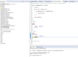
    Even if i2cLib_FIFO_polling.c is executed, it stops at fail () as shown in the attached image. Do I need to take any other steps to get the sensor value?

  • Hi,

    You will need to make changes to the code in Main() to match your I2C sensor. Like changing the write/read commands and sequence, configured slave address, etc.

    The project's main application file, 'Example_2806xI2C_eeprom_polling.c', is designed to interface with a completely different I2C EEPROM device by default. You need to tailor your application for your specific sensor.

    What I've been meaning is you can utilize the driver in the 'i2cLib_FIFO_polling' files for your project, making use of the below struct & functions:

    //
    // Typedefs
    //
    struct I2CHandle
    {
        Uint16 SlaveAddr;           // Slave address tied to the message.
        Uint16 *pControlBuffer;     // Pointer to control bytes buffer
        Uint16 NumOfControlBytes;   // Number of control bytes in message
        Uint16 *pMsgBuffer;         // Pointer to message buffer
        Uint16 NumOfDataBytes;      // Number of valid data bytes in message.
        Uint16 Timeout;             // I2C Timeout variable
    };
    
    //
    // I2C function prototypes
    //
    Uint16 I2C_MasterWrite(struct I2CHandle *I2C_Params);
    Uint16 I2C_MasterRead(struct I2CHandle *I2C_Params);

    Best,

    Kevin

  • hi, Kevin

    You said that you will use the "i2cLib_FIFO_polling" function and structure.
    It's already implemented that way in "Example_2806xI2C_eeprom_polling.c" and I don't know where to work.

    However, if you execute it as it is, it will still be stagnant with fail ().

    Please tell me what I should do now to display the sensor value of SparkFun.

  • Hi,

    if you execute it as it is, it will still be stagnant with fail ().

    As I've mentioned, you will need to make changes to the code in the main project file "Example_2806xI2C_eeprom_polling.c" or wherever the main() function resides in your custom project. the example will not work by default with your specific I2C device because the read/write commands need to be tailored for your specific I2C device.

    Please tell me what I should do now to display the sensor value of SparkFun.

    You need to review your SparkFun sensor datasheet and develop your main() application code (using the functions / framework provided) to correctly interface with the I2C slave device. I will not do this for you, besides the hard part of developing an I2C driver is already done in "i2cLib_FIFO_polling".

    Best,

    Kevin

  • I now know that I should change the main function.
    However, since I am a beginner in the program, I do not know where and what is missing.

    Can you give me some more specific tips?
    It would be helpful if you could provide us with sample code.

  • Hi,

    I checked the datasheet of your "SparkFun (PID 14607) Grid-EYE Infrared Array" and unfortunately there is not a lot of information on how to interface with the device. The best guidance I can give is to download the Arduino SW library SparkFun provides (link below) for the device and port the general SW and functions to your F2833x device.

    https://github.com/sparkfun/SparkFun_GridEYE_Arduino_Library

    You can utilize the "i2cLib_FIFO_polling" I2C driver structure/functions to make this easier. TI will not do the porting effort for you.

    best,

    Kevin