This thread has been locked.

If you have a related question, please click the "Ask a related question" button in the top right corner. The newly created question will be automatically linked to this question.

TMS320F28379D: Motor locks up in level 4 when using custom IDDK board with Control Suite

Part Number: TMS320F28379D

I would like to preface this with the reason why I'm using Control Suite instead of MotorControlSDK - I have to use a BiSS encoder and MCSDK doesn't support it yet.   

In relation to my problem itself - I have tested my motor in levels 1, 2, and 3 and everything works correctly as far as I can tell. The encoder position graph matches rg1.Out, the Alpha and Beta signals are 90deg out of phase and Alpha is exactly the same as phase A current.  

However, when I try to run the motor in Level4, the motor gets locked and I cannot move it by hand. Below is the debugging I've tried to do. Please let me know if there are additional steps I should try  

If I reduce the Umax/min of the pid_Spd module so that the motor holding torque isn't too high, I'm able to manually force the motor past the point that it gets locked, but it gets locked at the next pole(I know this because it gets locked to 14 distinct positions which is the number of poles). This seems to imply that the phase currents are stuck at one angle and not moving forward.

If I lower the Umax/min further, to just 0.05, I'm able to rotate the motor by hand faster and more easily, and that causes the motor to spin a little before getting stuck again. Now, it rotates "backward" in a jerky movement and then gets locked at the same mechanical angle. It stops at exactly the same mechanical angle every time when configured like this. If I move it a little beyond this angle, it will do almost a full rotation and get stuck at the same angle again. 

If I flip the direction of the encoder by doing 1-ElecTheta, the motor is still stuck but now doesn't rotate at all as I mentioned above, simply gets stuck at the closest pole. 

On a different note, for redundancy/flexibility of manufacturing, I would like to use any 2 current sensors instead of just phase A and B sensors. How do I specify this in the code? I have already made the necessary changes and confirmed that I am able to measure all 3 current sensors but am unsure how to request the software to use a different set of current sensors. For now, I will choose manually which 2 current sensors to use before compilation. Also, how do I confirm that the motor has been wired with the correct wires connected to A, B, and C? 

Thanks
Chai

  • IDDK kit, if you are able to run level3, then level 4 should not present any new problem. Wondering if the position feedback is messed up. Can you check up on this.

    For flexibility with programming reg current sensors, it is a programmers choice. For example, in IDDK code, we are choosing between various current sensors in a certain way. That may not be the most smart way, but...

    Reg wiring sequence being right, in build level 2, we mention this. In open loop rotation, if the slope of angle feedback matches with reference, then the sequence is right.

  • So after a lot of testing, this is the results - 

    Some current sensor mapping was incorrect, this was resolved. Now, Levels 1 and 2 works fine(on second inspection, they didn't work exactly correct before).

    Level 3 only works if the bus voltage is kept at a specific voltage. If it's too low the motor vibrates and if it's too high the motor vibrates but it vibrates very aggressively compared to when the voltage is too low, almost like the motor is going to break apart.

    Level 4 behaviour is same as above, it still gets stuck in one position after doing a full rotation, the encoder data and rg1.Out signal has the same slope in level 2 so that is not the issue. I'm wondering if the issue is that the pi_iq, pi_id and pid_spd gains are unstable and cause this behaviour. Is there any recommendation on what to do to tune these so they are stable?

  • Level 3 should work fine regardless of voltage. Should not show much deviation. Well, try to reduce the PI gains in the current loop, that should smoothen it.

  • If the issue is resolved, can you click resolved and close the thread. Thanks.

  • Hi Ramesh

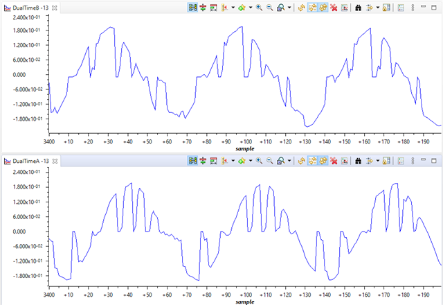
    I've identified a couple of different things that I believe are failures in the execution of the code. Firstly, when I operate at 10kHz switching frequency in Level 2, my motor angle as measured by the resolver is seen in the top graph and the rg1.Out variable is plotted below it. These are not properly in phase, that's not how it should be from what I understand, right?

    Secondly, my motor controller is designed to operate at 50kHz, so I raised the ISR frequency to 50kHz and saw 2 new issues. In the graphs below, I changed the dlog prescaler to be 25 instead of the usual value of 5 so that the graphs capture a similar number of samples per rotation.

    1. On occasion, the motor encoder position shifts to a new angle and continues from there. The encoder is very well-validated so I don't suspect that. The glitches are random and increase in occurrence at higher switching frequencies. It also occurs more frequently when I use a smaller dlog prescaler suggesting that perhaps data logging consumes precious CPU cycles and causing it to miss interrupts? I thought it might be a communication bottleneck and it's just CCS that is glitching, but the rg1 plot never shows any glitches so I don't think this is the case.

    2. The measured current glitches to 0 randomly mid-cycle before recovering to the actual value. The measured current signals are very clean and accurate at lower switching frequencies, and these glitches seem to only occur at ISR frequencies above ~35kHz so I'm suspecting a CPU loading issue. I am using the SDFM filter and have adjusted the OSR to be only 64, I also adjust the bit shift so the measured value is representable in 16bits. Are there any other settings I must change to ensure that the SDFM works correctly at higher ISR frequencies? In the graph below, I'm showing the current values for 2 of the sdfm filter outputs.

    By sticking to 10kHz, I moved on so I could test the PI controller gains as mentioned earlier. I reduced the iq and id loops to 0.2 and tested level 3 which seemed to work nicely at this Kp value, however, I now discovered a new issue that doesn't make any sense to me. When I plot the biss angle(bottom) and rg1.out(top) during level 3, it seems like the biss angle is not in sync or even the same frequency as the rg1.out variable. 

    When I use only proportional control for id and iq that seems to stop the "drifting" behaviour. However, the encoder and rg1.Out are not in phase with each other at all which might be the source of the issues in level 4?

  • 1. The forced angle and feedback angle need not be in sync. Most likely they may not be in sync, because the zero of forced angle and zero of encoder output can be at different instances. That is why we suggest to align during start up, so that electrical angle zero and mech angle zero can be lined up.

    2. The graph utility is likely to skip some times, consider it more as a poor man's graph tool for quick debugging. If you want better plots, use PWM dac to output variables of interest into analog form and monitor with a scope.

    3. In level 3, the motor runs based on available voltage and Iqref.and it is not supposed to sync with rg1.out. If you increase the voltage, the speed will increase and vice versa.

  • What could be the issue with the current measurement? Is that possibly a graphing utility error too? 

    I am still having the same trouble in level 4 where the motor gets locked at the mechanical angle of 0 and doesn't move. The motor also moves in the opposite direction to get to that angle compared to the direction it moves in level 2 and 3. What are some debugging steps to resolve this?

  • If you have a current probe, that will give best results.

    Reg the motor spinning in opposite direction in level 4 - I believe you already verified the sense of angle feedback and that of rg1.Out are same. If level 3 worked fine, then level 4 is just closing the speed loop and that does not make a fundamental change to the inner loop to behave like this. Suggest to verify how the speed loop is feeding Id and Iq references to current loop. Hope you can get some clue there.