A related question is a question created from another question. When the related question is created, it will be automatically linked to the original question.
If you have a related question, please click the "Ask a related question" button in the top right corner. The newly created question will be automatically linked to this question.
LAUNCHXL-F28379D: About ADC Result Registers of C2000 Microprocessor
I have basic problem about c2000 ADC. I know , data can be read adc result registers .(ADCRESULT0,1,2,3….15)
But my PIL( processor in the loop application) I wanted to manipulate(write) adcresult register(writable?) , I want to write 2040 value adcresult0 register in simulation , adc does not read the actual plant or connnection to the pin(I don’t want to apply external 3.3V top in ) , adc only read the simulation data from constant block(2040). In order to implement this , I used memory map block . For example I assigned the write value as 2040 and write to 0B00 address of adcresult0(because adc information is taken from adcin0)
ADC Informations:
Memory Block
I wrote 2040 value to ADCIN0 register(ADCRESULT0 register = 0B00
But I did not see 2040 value of the ADC output of the PIL(my processor in the loop simulation)
Finally ,
1-Can anyone explain are ADCRESULT registers writable or controllable from externally without any hardware ,(for example I don’t want to apply 3.3V ADCIN0 pin, this pin only changeable via simulation ? )
2-Is this 0B00 addresses correct for manipulate the ADCRESULT0 (ADCIN0) register? ( If first question false, this is insignificant. )
I really appreciate it if someone can help me in these regards. Thanks in advance for your answers.
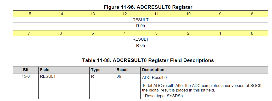
The ADCRESULT registers are read only. You cannot write to them. This is documented in the TRM, where the register is listed as being of type "R". For example, from SPRUHM8I:
As David said the ADC result registers are read only, so the Simulink tools won't be able to inject your constant value that way. For the purpose of debugging your system, I think you could just re-map where the results are fetched to match the memory where you've placed your constant(or other data).
I suppose another method would be to abstract your control calculations externally to the PIL block and feed the values in there.
In either case you could still set up the ADC as it would be your system, just to have the ADC Interrupts/EOCs for triggering/timing reasons.
Thank you for your answers and helps. Actually I want to mention about my problem more general.
I want to make PIL implementation using Matlab C2000 embedded coder
I successfully read EPWM value duty cycle(cmpa and time counter value ) according to this value I generated PWM on simulation beside on the Launchpad pin using EPWM . No problem here.
But I realized that there is no any input of the ADC block . According to PIL application voltage is getting from the voltage divider of plant circuit like a buck converter etc. But ADC block only accept the value via pin of the launchpad or microcontrollers.
For this reason I didn’t get the voltage value from the voltage divider circuit and insert it to ADC block. I want to implement this condition . I don’t want modeling a ADC block using matlab blocks , I want to use C2000 ADC block in order to analyze as if real value getting from voltage divider and adc makes sample,hold,quantization processes like a real application.
This is successfully done by PLECS like following figures;
You could see the simulation values(sensed values) enter the ADC block.
The inside of the adc block as follows;
This is an ADC type the way i want it to use my matlab PIL application(processor in the loop) . But as I mentioned above
The ADC block does not have no inputs in MATLAB like an ADC block have inputs as in the PLECS.
I don’t want to use PLECS because of the PIL modeling and out file creating difficulties(need to design some codes using code composer studio)
Compared to PLECS, Matlab out file generation and interface more simpler.
1-Do you have any works on this topic on your side((texas ınstruments )?
2-Are there any methods you can suggest?(I know you suggested some methods , but again I ask to you , you maybe give more general informations about this)
3- Will there be an improvement in this issue in the matlab c2000 embedded coder infrastructure in the coming years?
Our blocks that are shipped with C2000 support package are code-gen only. You cannot simulate these blocks to behave like a ADC peripheral.
Our ADC blocks always read the digital value as converted by the ADC peripheral of the MCU. So you need to code-gen to get these blocks to work either through external mode or as standalone.
We do have a project called SoC blockset that ship simulation ADC blocks.