This thread has been locked.

If you have a related question, please click the "Ask a related question" button in the top right corner. The newly created question will be automatically linked to this question.

TMS320F28035 control card in XDS100 v1 connection problem

Other Parts Discussed in Thread: TMS320F28035, CONTROLSUITE

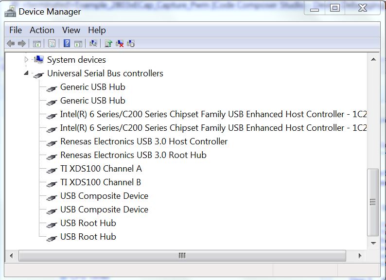
I'm using CCS 5.3 with a XDS100 v1 docking station and a TMS320F28035 control card in the docking station. 


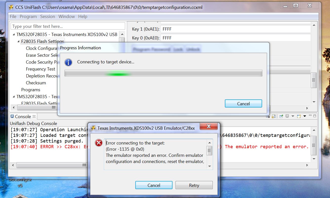
I can connect to an open loop hardware setup with the XDS100 v1 docking station... but when I move the the lab and try to connect to a different XDS100 v1 that has been put into a closed loop hardware setup for PFC I can NOT connect to the TMS320F28035 control card in the docking station.


I want to know what GPIO or JTAG pins have to be high and which ones have to be low for debuging.


This is what I have for voltage readings on my JTAG header on the open loop docking station that works.


J2

|`````````````````|

| 0v          0v  |

| 0v       3.3v  |

| 0v       3.3v  |

| 0v       3.0v  |

| N/C     3.3v  |

| 0v       3.3v  |

| 3.0v    3.3v  |

```````````````````

JTAG


This is what I have for voltage readings on my JTAG header on the closed loop docking station that does NOT connect.

J2

|`````````````````|

| 0v          0v  |

| 0v       3.3v  |

| 0v       3.3v  |

| 0v       3.0v  |

| N/C     3.3v  |

| 0v       3.3v  |

| 2.5v     3.3v  |

```````````````````

JTAG


the difference is 3.0v on the open loop dock station and 2.5v on the closed loop dock station on pin 6 of J2.


I'm going to try and pull up the voltage level on that 2.5v pin and see if that allows me to connect, but if that doesn't work I don't know what to do.


 This is the error:  Error connecting to the target: (Error -151 @ 0x0)

  • I tried bringing the 2.5v up to 3.3v and then tried to connect to the target... Did NOT work... Still can't connect to target...


    I opened up a brand new XDS100 v1 out of the box... put the brand new TMS320F28035 control card that came with it in the docking station ( was wearing EDS ground strap entire time)... STILL CAN NOT CONNECT TO TARGET.


    Power Switch is set in USB position... TMS320F28035 control card SW1, SW2, SW3 are in default positions.

  • Only thing I can think of is... I need a sperate license file for each docking station.... This seems like the only thing that could be causing this issue.


    Do I need a sperate license file for each XDS100 v1?


    Help please

  • Randy,

    "Do I need a sperate license file for each XDS100v1?"
    [BL] We have several licensing options, but none that should limit your targets like this

    In your above situation, are you using the on-board xds100v1 (that's physically on the Docking Station) or are you plugging in an external xds100v1? 
    -If you're using an external emulator I would recommend placing a jumper at J8 on the Docking Station.  This will disable the on-board xds100v1 emulator and reduce any chance of contention.
    -If you're using the on-board emulator, you may need to reprogram the xds100v1's EEPROM on the Docking Station that isn't working.  We rarely, but occasionally see this as an issue.  A guide to reprogramming the xds100v1 (on the Docking Station/Experimenter Kit) can be found here:
    http://e2e.ti.com/support/microcontrollers/c2000/f/171/t/21086.aspx

    Also, is the PFC board that you're trying to connect to a custom board?

    Let me know if, after trying some of the above, the issue remains.


    Thank you,
    Brett

  • Thanks,


    the link you provided fixed the problem.

  • Hello Brett,

    I have the same micro-controller as Randy does and same control Card. TMS320F28035 on ControlCard TMDSCND280351SO. Image of it is below. However, I don't have a docking station. 

    For about three weeks and I could not debug any example to my MC. I have a thread about this specific problem in link below 

    http://e2e.ti.com/support/microcontrollers/c2000/f/171/t/297616.aspx?pi269061=2

    BTW, I have my SW3 ON, SW1 ON, SW3 OFF. I also tried different combinations of switches 

    Here are some screen shot taking from the device manager...

    an Image of the error 

    I would appreciated if you or anyone else can suggest any solutions for this problem. 

    Best Regards,

    Osama 

  • Osama,

    This F28035 ISO controlCARD expects power from two sources:
    1) The emulator needs power and gets this from the USB cable. If powered, LD4 should be on.
    2) The MCU needs power and traditionally gets this through the DIMM connector.  If powered, LD1 should be on.

    It appears that only your emulation path is being powered.  Because of this your MCU is not being powered and therefore you are unable to connect to your MCU.

    If you have a baseboard (like the Docking Station), it will provide the necessary 5V to power the MCU.  If you don't have a Docking Station and don't wish to use one, you could solder a 0ohm resistor between TP3 & TP1 and a different one between TP4 & TP2.  This would allow the USB power to additionally power the MCU (or you could connect an external supply across TP1 and TP2).

    Schematics for the cCARD can be found in controlSUITE:
    \controlSUITE\development_kits\~controlCARDs\CC2803xISOHWdevPkg\

    Hopefully this helps.


    Thank you,
    Brett

  • Hello Brett,

    Finally I got it working. I am still wondering if it soldering two wire between TPs would affect the MCU when it is plugged in the PCB I have designed ?

    Regards,

    Osama 

  • Osama,

    By jumping power and ground across the TP test points, you are effectively defeating the isolation that exists between the emulator and the MCU.  If your baseboard is built such that the MCU will be running on the 'hot' side of some power electronics, then you will now want to be very careful because your computer will now run on the 'hot' side as well (this is especially true if your baseboard works at high voltages or on the AC mains).  We have seen computers that have been damaged if everything is not thought through thoroughly. 

    This is why we decided to have this controlCARD be powered the way it is.

    If your baseboard runs on low voltage, then having no isolation between the emulator and the MCU may be okay.  As the engineer, you will have to make the proper decision for your situation.


    Thank you,
    Brett

  • Hello Brett,

    I was testing the MCU after I uploaded an epwm example. I connected the ground of the oscilloscope to the GND pin in the MCU and the other prob to the EPWM1A output. Because of that, LD4 turned off, and the LD2 was blinking red. Since then, I could not flash any example. LD1 is not turning green anymore. 

    Do you think the MCU just burned ?

    Thanks,

    Osama 

  • Hi Osama,

    If LD4 and LD1 are not on than the controlCARD is not receiving power.  If you have plugged in and are supplying power than I would suspect a short.  I would recommend checking continuity between Power and Ground.

    If there is a short, it could be anywhere.  You'll just need to debug to try and find it.


    Thank you,
    Brett

  • Hi 

    Recently I bought 28035ISO control card and I was able to program the control card using code composer 4. But then I did some soldering on the power pcb. Tried again to program the control card it was showing error could not connect to the target it show this error. And tried connecting through other control card it was working now again other control card is also showing same error 

    C28xx: Error connecting to the target: (Error -1135 @ 0x0) The emulator reported an error. Confirm emulator configuration and connections, reset the emulator, and retry the operation. (Release 5.0.429.0)

    Thanks 

    Devendra