Hi All,
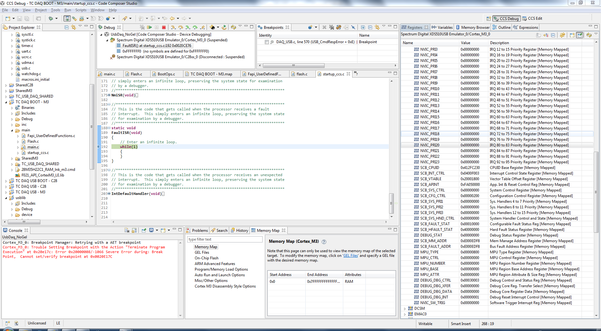
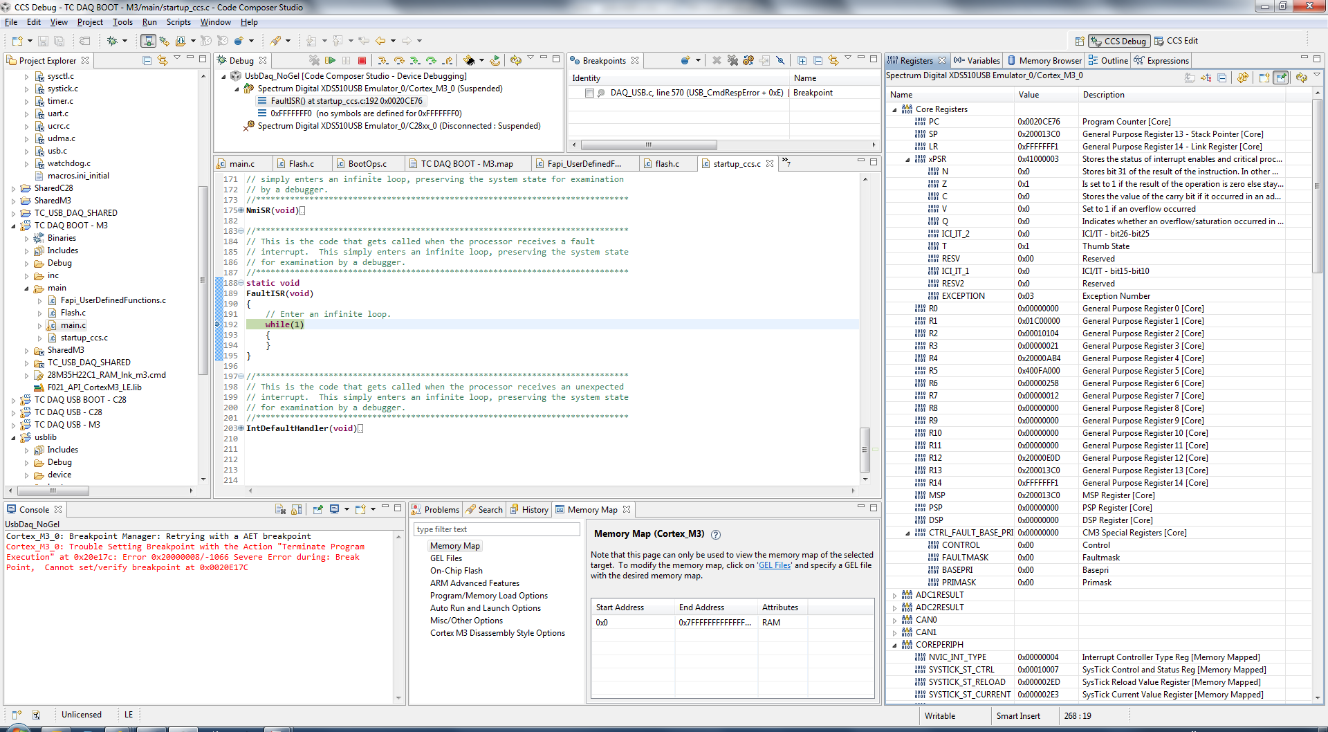
I would like to issue a software reset on the M3 and have the C28 and M3 both restart. I modified the blinky_dc example as a proof of concept, but it seems that only the M3 comes back from reset and hangs on IPCMtoCBootControlSystem(CBROM_MTOC_BOOTMODE_BOOT_FROM_FLASH);
Do I need to do something different to cause the c28 to come up correctly?
Thank you for your insights.
//###########################################################################
// FILE:   blinky.c
// TITLE:  blinky example.
//###########################################################################
// $TI Release: F28M36x Support Library v201 $
// $Release Date: Fri Jun  7 10:37:02 CDT 2013 $
//###########################################################################
#include <string.h>

#include "inc/hw_ints.h"
#include "inc/hw_memmap.h"
#include "inc/hw_nvic.h"
#include "inc/hw_gpio.h"
#include "inc/hw_types.h"
#include "inc/hw_sysctl.h"
#include "board_drivers/set_pinout_f28m36x.h"
#include "driverlib/debug.h"
#include "driverlib/flash.h"
#include "driverlib/ipc.h"
#include "driverlib/interrupt.h"
#include "driverlib/sysctl.h"
#include "driverlib/gpio.h"

//*****************************************************************************
//
//! \addtogroup dual_example_list
//! <h1>Blinky DC (blinky)</h1>
//!
//! Dual Core Blinky Example.  This example demonstrates how to run a
//! implement a standalone application on both cores.  Due to an errate in
//! the bootROM this example may not run correctly with the debugger connected.
//! To run the example, program both cores with their respective project and
//! then disconnect the debugger.  Set SW3 switch 1 to the down position
//! (disconnect TRSTn) as well as setting all 4 switches on SW1 to the down
//! position.  Cycle power and both LEDs should begin to blink.
//
//*****************************************************************************

#ifdef _FLASH
// These are defined by the linker (see device linker command file)
extern unsigned long RamfuncsLoadStart;
extern unsigned long RamfuncsRunStart;
extern unsigned long RamfuncsLoadSize;
#endif

//*****************************************************************************
// The error routine that is called if the driver library encounters an error.
//*****************************************************************************
#ifdef DEBUG
void
__error__(char *pcFilename, unsigned long ulLine)
{
}

#endif

//*****************************************************************************
//
// Blink LED3
//*****************************************************************************
int
main(void)
{

    volatile unsigned long ulLoop;

    // Disable Protection
    HWREG(SYSCTL_MWRALLOW) =  0xA5A5A5A5;

    // Sets up PLL, M3 running at 100MHz and C28 running at 100MHz
    SysCtlClockConfigSet(SYSCTL_USE_PLL | (SYSCTL_SPLLIMULT_M & 0xA) |
                         SYSCTL_SYSDIV_1 | SYSCTL_M3SSDIV_1 |
                         SYSCTL_XCLKDIV_4);

#ifdef _FLASH
// Copy time critical code and Flash setup code to RAM
// This includes the following functions:  InitFlash();
// The  RamfuncsLoadStart, RamfuncsLoadSize, and RamfuncsRunStart
// symbols are created by the linker. Refer to the device .cmd file.
    memcpy(&RamfuncsRunStart, &RamfuncsLoadStart, (size_t)&RamfuncsLoadSize);

// Call Flash Initialization to setup flash waitstates
// This function must reside in RAM
    FlashInit();
#endif

#ifdef _STANDALONE
#ifdef _FLASH
    //  Send boot command to allow the C28 application to begin execution
    IPCMtoCBootControlSystem(CBROM_MTOC_BOOTMODE_BOOT_FROM_FLASH);
#else
    //  Send boot command to allow the C28 application to begin execution
    IPCMtoCBootControlSystem(CBROM_MTOC_BOOTMODE_BOOT_FROM_RAM);
#endif
#endif

    // Enable clock supply for LED GPIOs
    SysCtlPeripheralEnable(LED_0_PERIPH);
    SysCtlPeripheralEnable(LED_1_PERIPH);


    // Give C28 control of Port C pin 6
    GPIOPinConfigureCoreSelect(LED_0_BASE, LED_0_PIN, GPIO_PIN_C_CORE_SELECT);

    // Disable clock supply for the watchdog modules
    SysCtlPeripheralDisable(SYSCTL_PERIPH_WDOG1);
    SysCtlPeripheralDisable(SYSCTL_PERIPH_WDOG0);

    // Enable processor interrupts.
    IntMasterEnable();

    // Set up the Pin for LED3
    GPIOPinTypeGPIOOutput(LED_1_BASE, LED_1_PIN);
    GPIOPinWrite(LED_1_BASE, LED_1_PIN, ~0);

    // Loop forever while the timers run.
    unsigned int bigLoop = 5;
    while(bigLoop > 0)
    {
        //
        // Turn on the LED.
        //
        GPIOPinWrite(LED_1_BASE, LED_1_PIN, 0);
        //
        // Delay for a bit.
        //
        for(ulLoop = 0; ulLoop < 2000000; ulLoop++)
        {
        }
        //
        // Turn off the LED.
        //
        GPIOPinWrite(LED_1_BASE, LED_1_PIN, ~0);
        //
        // Delay for a bit.
        //
        for(ulLoop = 0; ulLoop < 2000000; ulLoop++)
        {
        }

        bigLoop--;
    }

    SysCtlReset();
}