This thread has been locked.

If you have a related question, please click the "Ask a related question" button in the top right corner. The newly created question will be automatically linked to this question.

Piccolo SPI SPISTE Question

Dear All,

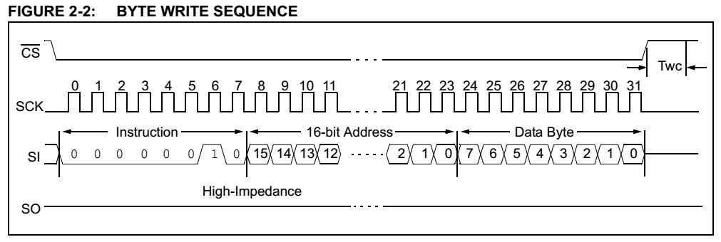
I am willing to interface an EEPROM to Piccolo F28069. I could not manage to send >16 bits over SPI link, with a single SPISTE pulse to the Slave. To describe it clearly, my memory device (e2prom) requires this command to be issued:

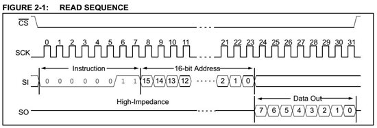
Could anyone advise, how to send this 32bit data in required format?

Regards,

Adnan Kurt

  • Adrian,

    The SPI port on F28069 will keep the SPISTE asserted (low) between back-to-back transfers in master mode.  This is documented in the device datasheet, SPRS698D, p.101, footnote A to Figure 5-27:

    "In the master mode, SPISTE goes active 0.5tc(SPC) (minimum) before valid SPI clock edge. On the trailing end of the word, the SPISTE will go inactive 0.5tc(SPC) after the receiving edge (SPICLK) of the last data bit, except that SPISTE stays active between back-to-back transmit words in both FIFO and non-FIFO modes."

    What this means is you need to keep the transmit buffer full.  In both FIFO and non-FIFO mode, the second 16-bit word must be written to TXBUF before the first word completes transmission.  This will eliminate the gap between transmit words, and keep SPISTE asserted.

    Regards,

    David

  • David thanks for your advise. It gets better now. I have two questions more:

    1. In spruh18d -F28069Technical manual, it reads

    "8. FIFO status bits. Both transmit and receive FIFOs have status bits TXFFST or RXFFST (bits 12− 0)
    that define the number of words available in the FIFOs at any time. The transmit FIFO reset bit
    TXFIFO and receive reset bit RXFIFO will reset the FIFO pointers to zero when these bits are set to 1.
    The FIFOs will resume operation from start once these bits are cleared to zero"

    on page 849. And on page 861

    "13 TXFIFO Reset          Transmit FIFO reset
                                 0          Write 0 to reset the FIFO pointer to zero, and hold in reset.
                                 1          Re-enable Transmit FIFO operation"

    How should we approach?

    2. How should I check, whether there is a byte received into buffer (yes, I've set the word length to 8bits)? 

    This is what I am trying now:

     spi_xmit(0x0000); // Dummy command to read 8Bit
    // Wait until FIFO is empty
    while(SpiaRegs.SPIFFTX.bit.TXFFST >= 0) { }
    // Wait until data is received
    while(SpiaRegs.SPIFFRX.bit.RXFFST <1) { }
    rdata = SpiaRegs.SPIRXBUF;


    However, I see more than 2 words -probably remnants of previous transmission data (RHS 8 bits?) which does not correspond to real alarm.

    3. This one is extra :). In order to send >16bits within a single SPISTE pulse, I had to make SPIFFCT registers' FFTXDLY delay bits to zero. Otherwise, SPISTE pulses are generated for each word. 

    Best Regards,
    Adnan Kurt

  • Adrian,

    On 1) You're right, there is inconsistency in the documentation.  I reported this for correction.  Page 861 is correct (i.e., set TXFIFO bit to 0 for reset, 1 for normal operation).

    On 2) I'm confused on why you're bothering to use the FIFOs if you're going to transmit one byte at a time and poll.  But regardless, if I take your code at face value:

    spi_xmit(0x0000); // Dummy command to read 8Bit
     // Wait until FIFO is empty
     while(SpiaRegs.SPIFFTX.bit.TXFFST >= 0) { } // Wait until data is received
     while(SpiaRegs.SPIFFRX.bit.RXFFST <1) { }
     rdata = SpiaRegs.SPIRXBUF;

    You are writing a single dummy word to the SPI TXBUF, then polling TXFFST until ALL words have been emptied from the TX FIFO.  At this stage, the last such word is still in the process of being shifted out of the SPIDAT register.  You then poll RXFFST until a word arrives.  So based on the above code, there should be only a single receive word.  If you have more words in the RX FIFO, then they are from earlier transactions that you did not read out of the RX FIFO.  Did you record the value of RXFFST prior to calling spi_xmit()?  That might help you debug.  It would show how many words are already in the RX FIFO.  Then the question is what are those words doing in there?  You would have had to have made previous SPI transactions.

    On 3) Yep, this makes sense.

    Regards,

    Davi


  • Thanks David.

    Concerning the second question: I need to use FIFO to transmit various length seamless data (8bit, 16 bits, and 32 bits) with uninterrupted SPISTE pulse. Sİnce I have to send 8 bit command to the e2prom, and i have to put Left Shifted 8 bit value to the buffer as advised in user's guide. So, remaining 8 bits are kept in FIFO (hope i have understood it correctly). Those built the garbage, I thought. Your advise to make note of "RXFFST prior to calling spi_xmit()" will be a better technique, thanks alot.

    Regards,
    Adnan

  • Adrian,

    Adnan Kurt said:
    Sİnce I have to send 8 bit command to the e2prom, and i have to put Left Shifted 8 bit value to the buffer as advised in user's guide. So, remaining 8 bits are kept in FIFO (hope i have understood it correctly).

    Not quite.  The entire 16-bit value in the lowest level of the FIFO will get transfered into the SPIDAT register (the shift register) when it is transmitted.  If the SPI is configured for 8-bit data length, then only the most-significant 8 bits will be shifted out of SPIDAT.  After transmission, the least-significant original byte will end up in SPIDAT as the now most significant byte, and the data received from the other SPI device will be the least-significant byte.  In other words like this:

    SPIDAT when transmission is about to start: [1234xxxx]

    SPIDAT when transmission is completed: [xxxx5678]

    where the 1234 is what you wanted to transmit, and the 5678 is what you received from the other SPI device.  Normally, people will shift the data they are transmitting so that the x's are all zeros.  That just makes it easier when you go to handle the received byte.  But, the SPI port doesn't know or care what value the x's have.

    Regards,

    David

  • Thanks David. Sorry for taking your time, but if you would reconsider the waveform I have attached to the initial message, the scheme that you suggest would not work, right?  It seems, 8bit command embedded into a 16bit value would not work easily, the way you explain.

    Regards,
    Adnan

  • Adrian,

    Your first post on Feb. 11 said "I have to send 8 bit command to the e2prom" so I assumed you had the SPI configured for 8-bit data length.  If you want to send a 32-bit value, you need to configure the SPI for 16-bit data length and send back-to-back words (so that SPISTE does not toggle, which you said is a requirement).  You cannot configure the SPI for both 8-bit and 16-bit data length.  It has to be one or the other.

    What are the EEPROM requirements for a transaction in terms of data sent and data lengths?

    - David


  • David, that's true. A write signal scheme is:

    Before this sequence, an 8-bit WriteEnable command must be send and SPISTE must be driven high. So, that forced me to set SPI to 8-bit wide, and when writing, I send 4 off 16bit words, which were 8bit values left shifted. eg. 0x1234000, high byte corresponding to the commands, address values, etc. 

    So, it works well. The only thing to take care of is those FIFO garbage.

    Best,

    Adnan

  • Hi David,

    Can you please suggest how I can receive a 32 bit data as well? I am using the 28035 and would like to send and receive unbroken 32 bit data? Please let me know..

    Kind regards,

    Bartho

  • "In the master mode, SPISTE goes active 0.5tc(SPC) (minimum) before valid SPI clock edge. On the trailing end of the word, the SPISTE will go inactive 0.5tc(SPC) after the receiving edge (SPICLK) of the last data bit, except that SPISTE stays active between back-to-back transmit words in both FIFO and non-FIFO modes."

    This is only valid on 28069, not on 28035 devices, right?
    I did not find this annotation in the sprug71b 28035 SPI description - and I did not see this on my scope. Even when transmitting back-to-back, the SPISTE pin goes high in between the 4 16 bit words.

  • Stephan,

    Please refrain from resurrecting old posts. If you have questions on an old post (especially 2 years old) create a new post, link to the original, and "mention" the person you are addressing your request to. This helps us track these posts much better.

    To answer your question, the timings are noted in the Datasheet, not the User Guide chapter. If the SPISTE is toggling, I suspect that you are not truly transmitting the words back-to-back. are you using the FIFO or not? What are you using to determine when to transmit the next word?

    -Mark

  • Sorry, I will remember that for future posts.

    I am using FIFO and doing 4 consequent writes to the SPITXBUF register. It's from C-Code, but I have controlled in the assembly output that the writes only take 2 instructions.
    The transmit is done every 100usec, 4 16-bit words (64usec); baudrate is 1MBaud.
  • After playing with the SPI settings a little bit, If found it myself: SPISTE for > 16 bit is also possible on the 28035.
    My problem was that I set a TXDelay in SPIFFCT > 0. After setting TXDLY=0, it works.
  • Glad to see that you figured it out.

    Yes, FFTXDLY will insert a delay in between each word transmitted.

    Just to note. This same behavior is present on all C2000 SPI modules. If you at the C2000 Real-Time Control Peripherals Reference Guide (SPU566) you will see that each device has the same SPI module. The core behavior will be the same across devices, though there are some small changes and improvements depending on the device used.

    -Mark