This thread has been locked.

If you have a related question, please click the "Ask a related question" button in the top right corner. The newly created question will be automatically linked to this question.

Smooth phase-shift from 0° to 180° - F28069

Hello,


I'm working on a project where I need phase shifted PWMs. Right now I'm using HRPWM on all the modules from EPWM1 up to EPWM8. EPWM1 is the master which generates a SYNC signal when CTR = ZERO. The phase shift of the master is of course fixed to 0°. For all of the other modules I need smooth phase-shift transitions between 0° and 180°.


Let me further explain how I configured my EPWM modules. I'm using up-down-count on all modules. The MCU is running at 90MHz and the TBPRD is set to 450 which equals a frequency of 100kHz. I can't use the deadband module because I'm using HRPWM, so I'm using CMPA and CMPB for creating a deadtime. For example the dead-time is 200ns. That means that EPWM1 has a CMPA and CMPB of 234 and EPWM2 a CMPA and CMPB of 216. The other modules are configured the same way.


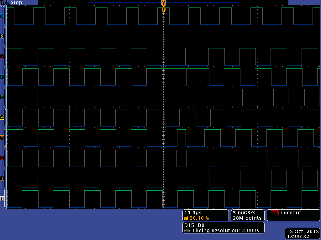
Now begins the problem. When I'm raising my phase shift and come to the two critical points of TBPHS = 216 or 243 the PWM jumps a compare event and the signal is completely screwed up. You can see it here in this picture:


This PWM signal will result in a shoot-through and kill the MOSFETs.

I tried to force a compare event when this happens and it kind of works. I force both signals to high (the PWM will be inverted externally), so a shoot-through will not happen. But that is not good enough. The signal still is completely screwed up and practically unusable.


So...is there an elegant way to solve this problem? Only using up- or down-count method doesn't work either. The cause of the problem are the 2 cycles delay between master and slave PWM modules (at least I think), so it won't really go away with another count method.


Thanks

  • Hi,

    Did you try configuring TBPHS register instead of TBCTR?

    Regards,
    Gautam
  • Hello Gautam,

    I'm using the TBPHS registers for the phase shift. I'm not changing TBCTR at all.

    I tried a lot of things in the meantime but I guess there is no solution for this problem at all.

    Regards,

    Milad

  • Hi Milad,

    Are you able to provide a code sample of your EPWM configuration and how you are changing the CMP / TBPHS value?

    Thanks,

    Kris
  • Hi Kris,

    here is the EPWM Configuration:

    Uint16 j;
    
    	for (j=1;j<=8;j++)
    	{
    (*ePWM[j]).TBPRD 						= PWM_100KHZ_PRD_CMPUPDOWN;	// Period = 900 TBCLK counts
    (*ePWM[j]).CMPA.half.CMPAHR 			= (0 << 8);             // initialize HRPWM extension
    
    		if(j == 1)
    		{
    			(*ePWM[j]).TBPHS.half.TBPHS 		= 0; 				// Set Phase register to zero
    			(*ePWM[j]).TBCTL.bit.PHSEN 			= TB_DISABLE; 		// Master module
    			(*ePWM[j]).TBCTL.bit.SYNCOSEL 		= TB_CTR_ZERO; 		// Sync down-stream module
    		}
    		else
    		{
    			(*ePWM[j]).TBPHS.half.TBPHS 		= 2; 				// Set Phase register to 2 to compensate for delay between master and slave PWM
    			(*ePWM[j]).TBCTL.bit.PHSEN	 		= TB_ENABLE; 		// Slave module
    			(*ePWM[j]).TBCTL.bit.SYNCOSEL 		= TB_SYNC_IN; 		// Sync input from master
    		}
    		(*ePWM[j]).TBCTL.bit.PHSDIR				= 1;				// Count up after sync event
    		(*ePWM[j]).TBCTL.bit.PRDLD 				= TB_SHADOW;
    		(*ePWM[j]).TBCTL.bit.HSPCLKDIV 			= TB_DIV1; 			// Prescaler = 1
    		(*ePWM[j]).CMPCTL.bit.SHDWAMODE 		= CC_SHADOW;
    		(*ePWM[j]).CMPCTL.bit.SHDWBMODE 		= CC_SHADOW;
    		(*ePWM[j]).CMPCTL.bit.LOADAMODE 		= CC_CTR_ZERO_PRD; 		// load on CTR=Zero
    		(*ePWM[j]).CMPCTL.bit.LOADBMODE 		= CC_CTR_ZERO_PRD; 		// load on CTR=Zero
    
    		if((j == 1 || j == 3))
    		{
    			(*ePWM[j]).CMPA.half.CMPA 			= PWM_DUTYCYCLE_50_CMPUPDOWN + DeadTimeInTicks_HV/2; // Set 50% fixed duty
                            (*ePWM[j]).AQCTLA.bit.CAU                      = AQ_CLEAR;            //LOW on CMPA up
    			(*ePWM[j]).AQCTLA.bit.CAD 			= AQ_SET;			//HIGH on CMPA down
    		}
    		else if((j == 5 || j == 7))
    		{
    			(*ePWM[j]).CMPA.half.CMPA 			= PWM_DUTYCYCLE_50_CMPUPDOWN + DeadTimeInTicks_LV/2; // Set 50% fixed duty
                            (*ePWM[j]).AQCTLA.bit.CAU                      = AQ_CLEAR;            //LOW on CMPA up
    			(*ePWM[j]).AQCTLA.bit.CAD 			= AQ_SET;			//HIGH on CMPA down
    		}
    		else if((j == 2 || j == 4))
    		{
    			(*ePWM[j]).CMPA.half.CMPA 			= PWM_DUTYCYCLE_50_CMPUPDOWN - DeadTimeInTicks_HV/2;    // set duty 50% initially
    			(*ePWM[j]).AQCTLA.bit.CAU			= AQ_SET;			//HIGH on CMPA up
    			(*ePWM[j]).AQCTLA.bit.CAD 			= AQ_CLEAR;			//LOW on CMPA down
    		}
    		else if((j == 6 || j == 8))
    		{
    			(*ePWM[j]).CMPA.half.CMPA 			= PWM_DUTYCYCLE_50_CMPUPDOWN - DeadTimeInTicks_LV/2;    // set duty 50% initially
    			(*ePWM[j]).AQCTLA.bit.CAU			= AQ_SET;			//HIGH on CMPA up
    			(*ePWM[j]).AQCTLA.bit.CAD 			= AQ_CLEAR;			//LOW on CMPA down
    		}
    
    
    		(*ePWM[j]).TBCTL.bit.CTRMODE 			= TB_COUNT_UPDOWN; 		// Symmetrical mode
    
    		EALLOW;
    		(*ePWM[j]).HRCNFG.all = 0x0;
    
    			
    		(*ePWM[j]).HRCNFG.bit.HRLOAD  	= HR_CTR_ZERO;		//HR_CTR_ZERO_PRD; 	// Load on CTR = 0 and CTR = TBPRD
    		(*ePWM[j]).HRCNFG.bit.AUTOCONV 	= 1;              	// Enable autoconversion for HR period
    		(*ePWM[j]).HRCNFG.bit.EDGMODE 	= HR_BEP;          	// MEP control on both edges
    
    		(*ePWM[j]).HRCNFG.bit.CTLMODE 	= HR_PHS;          	// Selects the register (CMP/TBPRD or TBPHS) that controls the MEP:
    		(*ePWM[j]).HRPCTL.bit.TBPHSHRLOADE = 1;          	// This bit allows you to synchronize ePWM modules with a high-resolution phase on a SYNCIN, TBCTL[SWFSYNC] or digital compare event
    		(*ePWM[j]).TBCTL.bit.PHSDIR 	= 1;				// count up after SYNC event and the new value of the phase (TBPHS) is loaded.
    		(*ePWM[j]).TBPHS.half.TBPHS 	= 2;				// initial - coarse phase offset relative to ePWM1


    		(*ePWM[j]).HRPCTL.bit.HRPE 		= 1;                // 6. Enable high-resolution period control.


    		EDIS;
    
    }

    EPwm1Regs is the master (j == 1). Every other module is a slave. I set the phase shifts of each module in the CLA after some calculations.

    		EPwm3Regs.TBPHS.half.TBPHS = PS1;
    		EPwm3Regs.TBPHS.half.TBPHSHR = PS1_fine;
    		EPwm4Regs.TBPHS.half.TBPHS = PS1;
    		EPwm4Regs.TBPHS.half.TBPHSHR = PS1_fine;
    		EPwm5Regs.TBPHS.half.TBPHS = PS2;
    		EPwm5Regs.TBPHS.half.TBPHSHR = PS2_fine;
    		EPwm6Regs.TBPHS.half.TBPHS = PS2;
    		EPwm6Regs.TBPHS.half.TBPHSHR = PS2_fine;
    		EPwm7Regs.TBPHS.half.TBPHS = PS3;
    		EPwm7Regs.TBPHS.half.TBPHSHR = PS3_fine;
    		EPwm8Regs.TBPHS.half.TBPHS = PS3;
    		EPwm8Regs.TBPHS.half.TBPHSHR = PS3_fine;

    Can you spot the problem?


    Regards,

    Milad

  • Hi Milad,

    I believe this behavior is a result of newTBPHS values that cause the TBCTR to jump over the CMPA/B register values. To avoid this the only solution is to adjust the CMPA/B value or the TBPHS value for the PWM cycle where this jump may occur (adjusting these by one count is enough). This means that the code where TBPHS is being changed should also check if this condition (based on previous TBPHS value, new TBPHS value, and the CMPA/B value) may occur. You may also refer to this thread: https://e2e.ti.com/support/microcontrollers/c2000/f/171/t/22575

    Hrishi

  • Hi Hrishi,

    thanks for the tip. But wouldn't that only help if my old TBPHS value is just one count under the critical value? In case the old TBPHS is way under the critical value of CMPA/B, then this wouldn't work. I have to make a step from TBPHS << CMPA/B to TBPHS-1 = CMPA/B and then change the CMPA/B value. Or am I incorrect?

    Regards,


    Milad

  • Hi Milad,

    I am not quite sure I understand your question. I believe you have a fixed frequency operation. If it's not, I can point to my other posts on variable frequency with phase shift operation.

    Here's an example scenario for PWM1 and PWM2 configured in up-count mode. PWM1 time-base is the master that synchronizes PWM2 time-base on a PWM1 counter = 0 event. Let's assume a period value of 500 and a 40% duty cycle i.e. CMPA = 200. Let's assume the old TBPHS value (TBPHS2)  = 100 and the new value = 210. Finally, we will use a CTR = ZERO interrupt ffor PWM1 to update the phase value.

    When the new TBPHS value is calculated inside this interrupt, the code should check whether the new TBPHS may cause a jump in the counter value that might skip the CMPA event. In this case, when the PWM2 counter hits 100(old TBPHS2) it will receive a sync signal from PWM1 (TBCTR1 = 0) that will make the counter start counting from 210(new TBPHS2). This skips the CMPA value (200) if this value is not adjusted. If the above check comes positive the code should change the CMPA value to 'TBPHS2+1' (211) for just one cycle. The CMPA value should be changed back to 200 in the following cycle.

    Note that shadow loading of CMPA registers should be used. It is assumed that the counter is configured to count up after a sync event.

    I hope this helps.

    Hrishi


  • Hi Hrishi,

    thanks for your explanation. I think I understand now. I will try this and then report back later if it works.

    Regards,

    Milad

  • Hi Hrishi,

    did you verfiy that the code is working?

    I tried to do the solution you described and it doesn't work. There is still a long pulse. I change the PWM values in the CLA, but I don't think this will cause any problem.

    EDIT: Nevermind. There was an error in my code. But it only sort of works. If the steps are small, let's say from 234 to 235, it works fine. But big steps like from 0 to 300 still produces a huge pulse, which kind of makes sense. In this case I'll change my CMPA to 301 and this of course produces a big pulse...But shouldn't this pulse be limited to only one cycle? On the oscilloscope I still see the pulse spanning over two cycles.

    Regards,

    Milad

  • Hi Milad,

    In case of big jumps in phase shift the output will look like it is High/Low longer than intended but this is expected because of the phase shift effect on the PWM counter (counter has to count more or less to reach the period/AQ action). 

    It might help if you could draw up the expected and desired waveforms along with the time base counter.

    Hrishi

  • Hi Hrishi,


    I know that this is normal. It also probably won't affect the operation. But I still have some strange things happening. You can see it here in the picture:


    Channel 6 and 7. I'm not exactly sure what is happening. This is a jump from a phase shift of 3 (PSDIR = 1) to 448 (PSDIR = 0). I'm doing the check you have suggested and I also check the PSDIR and change the limits accordingly.

    Regards,

    Milad