This thread has been locked.

If you have a related question, please click the "Ask a related question" button in the top right corner. The newly created question will be automatically linked to this question.

Generating 3 level PWM for T type module


Hello,

I'm trying to generate 3 level PWM for the T- type power IGBT module.

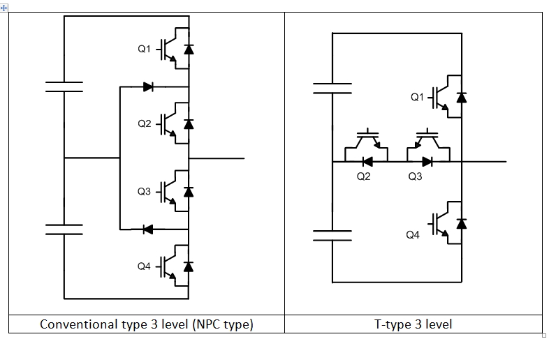
As you know, a 3 level IGBT module have 4 switches for a phase. I assigned two ePWM modules for one phase (for 4 switches) which means one ePWM generates two complementary signals to drive two switches. For the conventional type (NPC type), as long as two gating signals, Q1 and Q3, Q2 and Q4 (generated from the same ePWM) are complementary with a dead time, there is no case that the bridge shoot-through happens.

Similarly, for the T-type module, Q1 and Q3 gating signals can be generated using two complementary signals (using one ePWM), and the same thing for Q2 and Q4), However, How can we make sure that Q1 and Q4 never turn on at the same time.  As far as I know, TI ePWM does not support this function (correct ??).            

How can we make sure that Q1 and Q4 never turn on at the same time ??

Thank you

  • Hi,

    My team hasn't done a lot directly with multi-level inverters yet.  However, we do have customers that have.

    The ePWM peripheral, on its own, will not be able to completely remove the risk of the Q1-on, Q4-on destructive state.  It would largely be up to software to make sure that this destructive state does not occur.

    If you want extra logic protection, it is possible on some of our newer devices, like the F2837x family, to bring the PWM inputs into a GPIO pin.  In the GPIO logic, the signal has the possibility to get inverted before getting passed on.  This signal can then go to the INPUTXBAR and then to the Digital Compare submodule of the ePWM.  Here you can use the TZDCSEL register to AND two signals together.  This can then be used to feed into the TZ submodule and force a cycle-by-cycle or one-shot trip - which could be configured to trip the PWMs into their safe state.

    The below link is a combination of some of the diagrams in the F2837x TRM and should help to tell the story I briefly described above.  Perhaps this can give you some ideas.

    /cfs-file/__key/communityserver-discussions-components-files/171/AdvancedTrippingInF2837x.pptx

    Hopefully this helps!


    Thank you,
    Brett

  • Out of curiousity, IL DO YOO92, when would you expect a shoot through scenario in Q1 and Q4 for the T-Type structure? To my understanding and verified on own prototypes, if the PWM is implemented correctly, no software shoot through between Q1 and Q4 will occur.
    A shoot through may be possible due to EMI concerns, though, for instance due to false triggering. But that would clearly be a different issue to look at and to solve.

    Kind regards,
  • I appreciate you for the answer.
    I'll try the way you suggest in the second part.
    what would be a possible way to prevent it in the software ?

    Thank you
    Il Do Yoo
  • Thank you for the answer.
    As you said, this one should not happen the PWM is working normally. However, at any abnormal situation, can we guarantee the shoot-through never happen by PWM pattern ?

    Thank you
    Il Do Yoo
  • It depends on what you consider an abnormal situation.