This thread has been locked.

If you have a related question, please click the "Ask a related question" button in the top right corner. The newly created question will be automatically linked to this question.

CCS/LAUNCHXL-F28379D: Compiling "Sensored FOC PMSM Motor Control Project" located in "C:\ti\controlSUITE\development_kits\TMDSIDDK_v2.0"

Part Number: LAUNCHXL-F28379D
Other Parts Discussed in Thread: CONTROLSUITE

Tool/software: Code Composer Studio

Hello,

I am attempting to run the "IDDK_PM_Servo_F2837x_v2_00_00_00" example project for the IDDK located here: C:\ti\controlSUITE\development_kits\TMDSIDDK_v2.0\IDDK_PM_Servo_F2837x_v2_00_00_00
I am doing this because the LEVEL1 #define located in "IDDK_PM_Servo_F2837x-Settings.h" will allow me to run 6 ePWM signals to an oscilloscope in an open loop control.

The software guide is located here: C:\ti\controlSUITE\development_kits\TMDSIDDK_v2.0\IDDK_PM_Servo_F2837x_v2_00_00_00\~Docs
I am on page 21 on Step "LEVEL1" of the walkthrough
I attached the above PDF in this post.

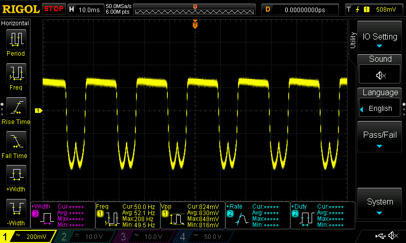
I am seeing a very strange output waveform on ePWM1A. (Pin J4-Pin40 on the F28379D Launchpad)

I set the control variables in the expressions window through importing the "Variables_IDDK_Level1.txt" file into the expressions window by right-clicking and selecting import within the expressions window.

I included a picture of the output waveform on Pin40 of the launchpad.

QUESTION:

1) WHY IS THE EPWM on Pin40 of the launchpad not a square wave, and also, why is the PWM centered and positive and negative? Shouldn't the PWM be between 0V and 3.3V?

I am saying this because if I attached a MOSFET gate to Pin40, then the MOSFET will not turn on if the voltage is <3V.

Thank you,

Keith

Sensored FOC of PMSM_IDDK_v2.pdf

  • 1. Looks like the scope is on a time scale of 10ms/div. The signal may have been acquired in some kind of filtering mode. Check it out.

    2. Secondly, the device is not meant to directly drive a MOSFET, and the high and low sides should be driven by a suitable inverter. May be the above signal is because of the drive config. Try removing the MOSFETs and just verify if you see the right pwm signal.

  • Thank you Ramesh!


    1) I investigated the oscilloscope and it was set to AC coupling, but after changing it to DC coupling, the voltage is still 0V to 1V.
    I need 3.3 or 3.0V to trigger the MOSFET gate driver IC I am using.
    I think you are correct with the PWM not being a square wave. The PDF walk through has strange torque feedback at open circuit load.

    PWM1B also exhibits the same behavior where it is only outputting a 0-1V waveform instead of a 0-3.3V waveform.

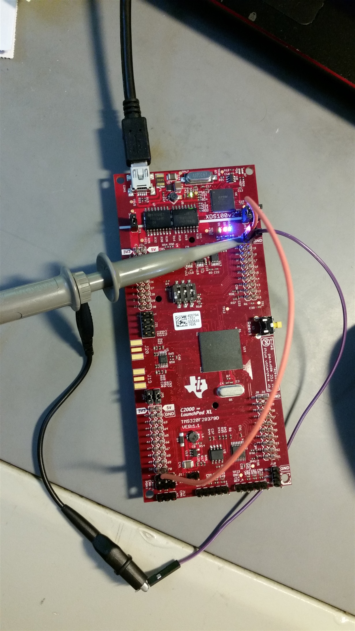
    Also, I forgot to remove a jumper I had from Pin40 to Pin 70 (ePWM1A to ADC_A1) from another test project.
    What I found curious was that when I removed the jumper, the PWM signal no longer showed up on the oscilloscope.
    If I reconnect the Pin40/Pin70 jumper, the PWM shows up on the oscilloscope.

    2) Is the PWM signal active low (am I required to have an external pullup on the ePWM1A output pin?

    The 
    It is almost like there might also be a floating ground? All of the jumpers are installed for the ground plane on the Launchpad F28379D.

    I attached a picture of the Launchpad with the jumper Pin40/Pin70 wire jumper installed.

  • I am still unable to see 6 PWM outputs from the microcontroller. PWMs 1H,2H,3H,1L,2L,3L are all reading 0V.
    I probed all the pins and found that pin 70 on the F28379D launchpad (Labelled AA1 on back of PCB) shows the attached waveform that looks like the intended Digital-To-Analog Converter (DAC) output).
    1) Why is the intended DAC output not on the DAC 1,2,3,4 pins on the launchpad?

    I also included a screen capture of the graphing of the Ta,Tb,Tc variables.

    2) How do I get the graphs to show up the same as the PDF walk through (I have the PDF walk through side-by-side with the CCS graphing)?
    I assume it is a sampling issue, but what settings in CCS do I have to change to view Ta,Tb,Tc correctly in CCS?