This thread has been locked.

If you have a related question, please click the "Ask a related question" button in the top right corner. The newly created question will be automatically linked to this question.

LAUNCHXL-F28379D: ADC

Part Number: LAUNCHXL-F28379D
Other Parts Discussed in Thread: TMS320F28379D

Hi,

I need to measure current from a LEM module. The output from the LEM is 0 ~ 5 V and I scaled it to 0 ~ 3 V by a voltage divider.

Now I am not quite sure about how to connect the LEM pins to the ADC pins of the MCU. I thought the connection should be in this way as follows. Does my connection look correct? 

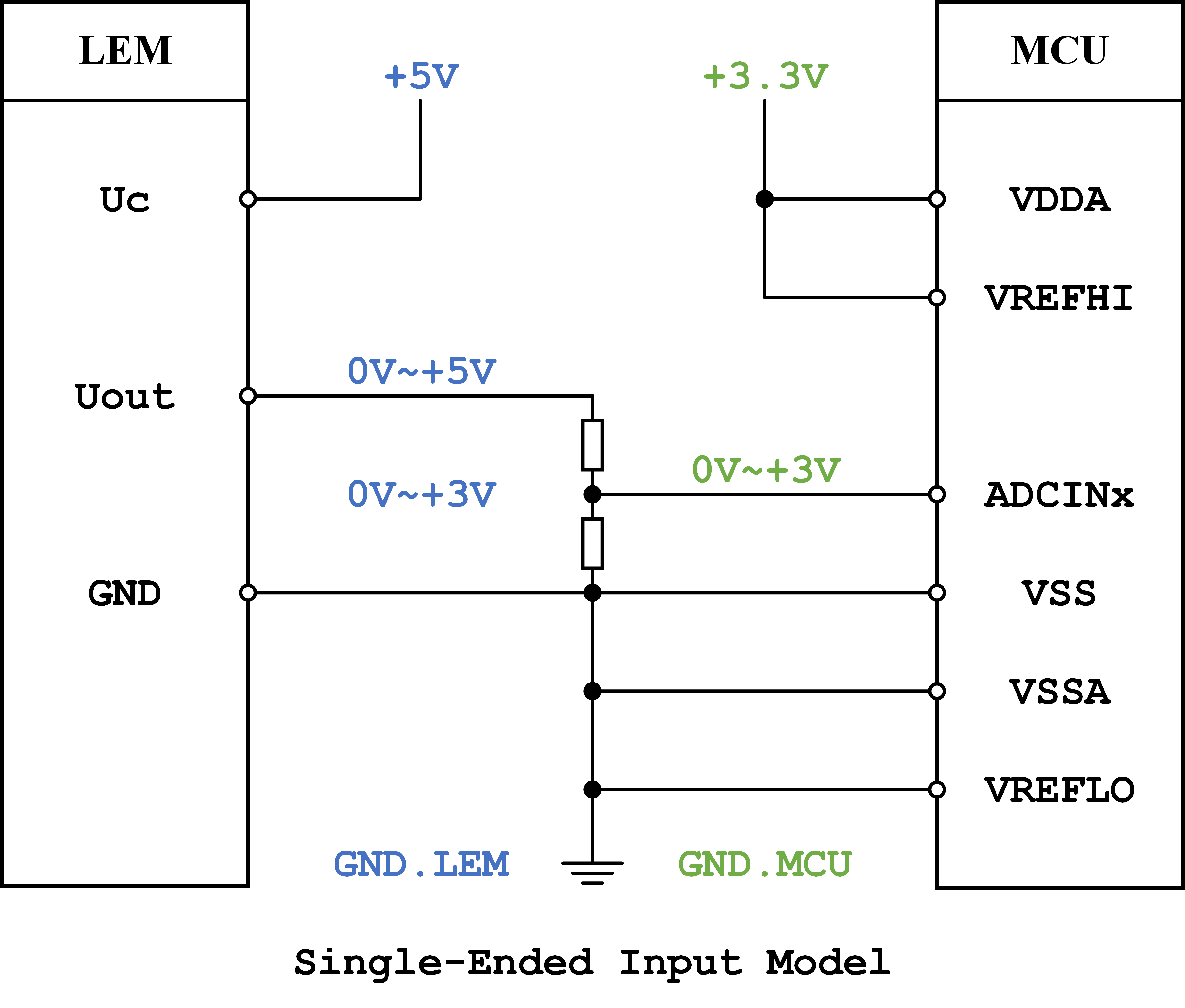
I heard that it is better to use Differential Input Model to reject the disturbance. However, I am not quite sure if it is possible to use Differential Input Model because the MCU and the LEM share the same ground in our case. Does anyone have any opinion or suggestion?

Thank you very much!

Sincerely,

Junfei Tang

  • Junfei,

    The single-ended connection should suffice, but you should be aware that connecting the VREFHI directly to VDDA (as opposed to a discrete voltage reference IC) may reduce the 12b precision.

    The 16b differential mode is possible, but you would need to convert the single-ended input signal (Uout) into a differential signal with a common mode voltage of VREFHI/2 for full-scale operation. The external reference tolerances (circuitry requirements) will also be stricter compared against the 12b mode.

    -Tommy
  • Hi Tommy,

    Thank you for your reply!

    My colleague and I are new users of TMS320F28379D, so we still have some questions.

    • We plan to use a "48 V - 3.3 V" DC-DC converter to provide 3.3 V to the VDDA of the MCU. If the VREFHI is not connected to VDDA, then should we use a voltage divider to provide VREFHI with 3 V from 3.3 V?
    • By "to convert the single-ended input signal (Uout) into a differential signal with a common mode voltage of VREFHI/2 for full-scale operation", do you mean, we should scale the 0~5 V to 0~3 V, and shift it up so that the voltage potential of the negative channel varies between 0~1.5 V whereas the voltage potential of the positive channel varies between 1.5~3.0 V?
    • In differential mode, should VSSA be connected to VSS? Should VSS be connect to the GND of the LEM?
    • In single-ended mode, should VSSA be connected to VSS? Should VSS be connect to the GND of the LEM?
    • We plan to place the MCU very close to a motor. And we think the motor should be a source of EMI. Is it necessary to use differential input mode in this case?

    Thank you very much!

    Sincerely,

    Junfei Tang

  • Junfei,

    The VREFHI pin will have spurious current requirements during ADC conversions. The VREFHI source voltage should have low impedance with a fast transient response time (either buffered with an op-amp or sufficiently decoupled with capacitors). The worry of connecting VREFHI to VDDA was primarily due to the switching noise that is common on DC converters. The voltage divider approach would not be recommended because it would have most of the switching noise and high impedance.

    The differential ADC expects the ADCINxP and ADCINxN signals to have both positive and negative polarity relative to each other. The absolute voltage for either signal should be kept between VREFLO and VREFHI. You can reference the Expected Conversion Results tables in the TRM for more details.

    For best precision, it makes sense to connect VSSA to the GND.LEM signal.

    VSSA can be connected to VSS either through a continuous plane or through a single point with isolated supplies. It is typically easier to manage a continuous plane.

    Single-ended ADCs are common in motor control. I don't think that it would be necessary to use differential unless you have very high precision requirements. EMI can usually be managed through good layout practices.

    -Tommy