This thread has been locked.

If you have a related question, please click the "Ask a related question" button in the top right corner. The newly created question will be automatically linked to this question.

F28M35H52C: Problem in making a jump to application section from a Bootloader

Part Number: F28M35H52C


Hi,

I am almost in end stages of completing a bootloader for C2000 Cortex M3 core. I require some help with regards to an issue i am facing in making a jump to application section of flash from Bootloader. 

What I have so far:

The bootloader has the ability now to read the data received through UART, parse the data and flash the data in to concerned address using TI Flash api library. For simplicity sake i have considered blinky m3 example to flash the from the Bootloader. I have selected intel HEX format with 32bit wide ROM and memory range. I am trying to send this generated HEX file using a python code from my host machine. 

Flash Memory Sectors considered:

Bootoader -> Sector N, M and L

Application -> Sectors K to A.

Issue i am facing:

Once I write the respective parsed hex file in to the Flash memory and try to make a jump in to the blinky application the console throws a message saying "No content in location 0xfffffffe". But my reset vector for blinky application lies in location 0x0022162B and this is where i am trying to jump. I could see the contents in Disassembly window as well. 

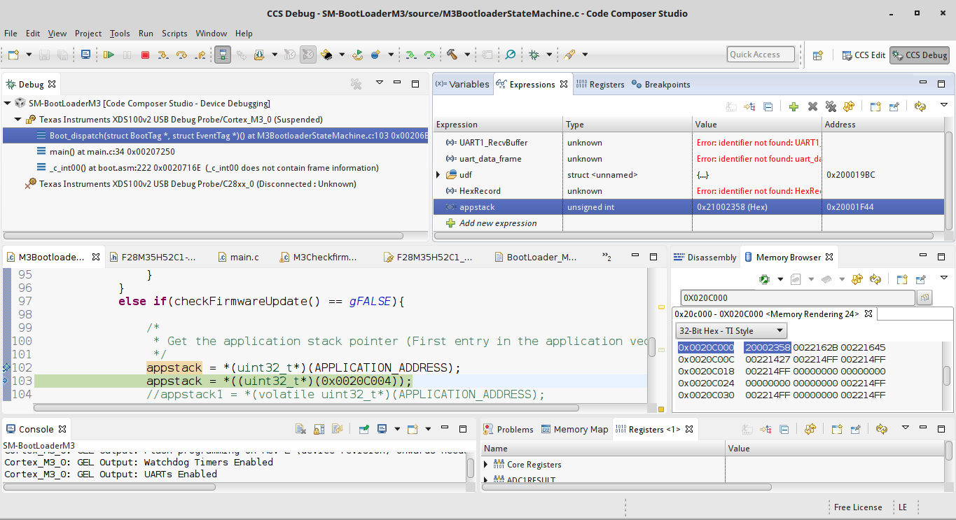
But what was not making sense was stack end address value of blinky application. This particular value when looked in vector table inside Memory region window after flashing is 0x20002358. But when i try to read the value from the Bootloader the value is 0x21002358 !! I can not understand whats going on here as i see the rite value in Flash Memory region but different value when i read it through software ??

Some Troubleshooting:

When i flash the blinky application program using TI flash utility by specifing sectors K to A and flashing Bottloader which is specifically for sectors N to L with out erasing blinky application, i could easily jump to blinky application with same reset vector address. But with out a problem in reading the stack end address which appears to be same as the one in Vector table. 

But the problem seems to occur if i try to erase and write the flash contents through Bootloader and try to make a jump. 

Below are some screenshots.

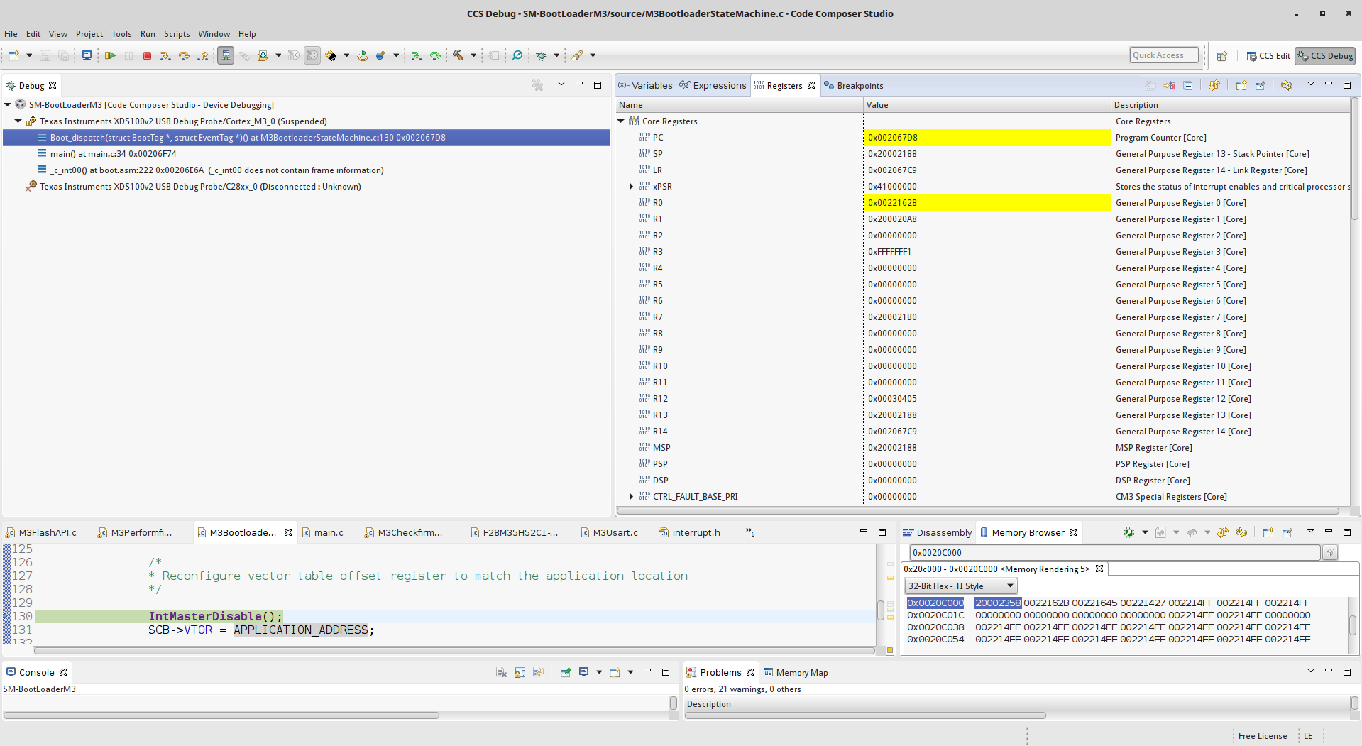
1. This is where i have captured appstack value. which shows a comparison btw what i read and whats in vector table address.  


2. What i see when i make a jump from Bootloader

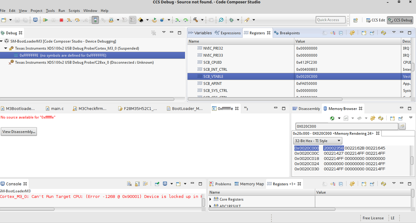
3. I tried to have a breakpoint on 0x0022162b to try step by step debugging in disassembly but this seem to not work for me either. 


Thanks  

  • Preetham,
    I don't fully understand the question with the Stack pointer from the vector table. The SP from the vector table will be initialized only at reset right? if you want to change the SP before branching to your application entry point you have to do that in SW.

    Secondly, at the end of boot loader you should be able to simply make a branch to your application entry point. Can you check if the address you are branching to has LSB set as '1'? I believe you will be using a hardcoded address as your applications entry point .

    Can you show the assembly or C code in boot loader that is branching to application? from the dis-assembly snippet it seems like you don't have the LSB of the address set.

    Hope this helps.

    Best Regards
    Santosh Athuru
  • Hi Santosh,

    Below are my reply,

    Santosh Athuru said:
    I don't fully understand the question with the Stack pointer from the vector table. The SP from the vector table will be initialized only at reset right? if you want to change the SP before branching to your application entry point you have to do that in SW.

    I am sorry if my question is misleading. As of now I am not trying to change the Stack Pointer value in anyway with in my Bootloader application. All i am trying to do now is Erase and Write the Flash contents with Blinky Application through the Bootloader and make a jump to the reset vector function of Blinky Application from where the application should spin off. 

    Santosh Athuru said:
    Secondly, at the end of boot loader you should be able to simply make a branch to your application entry point. Can you check if the address you are branching to has LSB set as '1'? I believe you will be using a hardcoded address as your applications entry point .

    This is something i have not thought about before i write the flash contents at the particular address. Should we do this because ARM Core Program counter needs this ??

    Santosh Athuru said:
    Can you show the assembly or C code in boot loader that is branching to application? from the dis-assembly snippet it seems like you don't have the LSB of the address set.

    Below are the lines of code i follow before i make any jump in to the application software. 

    Where APPLICATION_ADDRESS is a #define with value 0x0020C000. Now this is the address where Blinky Application vector tables starts from. So my appentry value below will be Blinky Application ResetISR address which is 0x0022162b. I verified this symbol address even from Blinky Application map file. 

    Should i now change the value of appentry to 0x0022162C before i make a jump? As you said i need to set the LSB of the address to 1. 

    /*
    * Get the application stack pointer (First entry in the application vector table)
    */
    appstack = *(uint32_t*)(APPLICATION_ADDRESS);

    /*
    * Get the application entry point (Second entry in the application vector table)
    */
    appentry = (funcptr) *(uint32_t*)(APPLICATION_ADDRESS + 4);

    /*
    * Reconfigure vector table offset register to match the application location
    */
    SCB->VTOR = APPLICATION_ADDRESS;

    Now when i try to read the value ( appstack ) of __STACK_END of blinky application which resides at 0x0020C000 it reads as 0x21002358 but the value is actually 0x20002358 both confirmed from memory view and blinky map file. This is what i was trying to explain in my question. 

    Now this looks like a stack overflow for me, can you please confirm if this true. May be this is the reason i am not able to jump to blinky application. 

    Thanks 

  • Preetham,

    as I understand, you are very close to get your application SW working, just few more steps to fix/correct :-)

    Below is the code I use on M3 when branching to an address. Try updating your SW to use similar to below.

    {
    entry_addr = 0x20004000; // just as an example

    //for the blx instruction
    // BLX instruction result in a UsageFault exception if bit[0] of Rm is 0.
    entry_addr |= 0x1;
    ((void (*)(void))entry_addr)();
    }

    Changing the Vector table offset doesn;t change the Stack pointer. The Stack pointer is only updated by the MCU from the vector table offset location on a reset vector fetch. When you update the vector table offset you should change the SP manually in SW code if you wish to use a different SP.

    There should be assembly instructions on how to get SP updated, please refer to ARM documentation.

    Hope this helps.

    Best Regards
    Santosh Athuru
  • Santosh,

    I tried your way which will increment the address of application RestISR. (from 0x0022162B to 0x0022162C).

    But i still could not  jump to the RestISR, I am still receiving the same error message as posted in my first question. 


    But what i do not understand is why is the Stack Pointer value when read displays 0x21002358 when the actual value seen in the memory window is 0x20002358 ?

    My observation:
    So when i only try and read the stack pointer value like below

    appstack = *(uint32_t*)(0x0020C000);

    I should read 0x20002358 but instead i read 0x21002358. This is where i guess problem lies. Can you help me understand this situation.

    Thanks

  • Preetham,

    0x22162B is actually the address with LSB (bit 0) set as '1', so you should be able to do the branch to that address . You don't have to increment the address, if the LSB (bit 0) is already set to '1' then the code snippet I put leaves the address same, doesn't increment it. From the dis-assembly snippet you put above in first post, it looks like you do have valid code.

    Can you check if you are disabling all the interrupts before you switch the VTABLE?

    What happens if you force PC to 0x2216A by modifying the PC register from CCS? and try to execute the B.W instruction at 0x22162A? Without changing any SP?

    What is the value of SP before you switch the VTABLE offset? It is really wierd that you are seeing 0x21002358 instead of 0x20002358.
    Does the same happen on any other part/board that you have? Yo uare changing the VTABLE offset in privileged mode as well because I can see that from the registers window in the snapshot, so this is right as well.

    can you put a snapshot of the SP and CPU registers window before you execute the branch and after you execute the branch to reset vector?
    the Address range 0x21xx_xxxx is invalid. Also before you switch the VTABLE and after you switch the VTABLE?

    I agree that we need to understand the SP issue first. Does this happen in any other project ? for ex:- if you just change the VTABLE offset


    Best Regards
    Santosh Athuru
  • Santosh,

    Just to give you an understanding on two different ways i am using to branch to application RestISR from the Bootloader.

    1. This is where i use TI's CCS integrated FLASH utility tool to write the contents only in the selected FLASH sectors. I achieve this by selecting project properties -> Debug -> Flash Settings -> under Erase Settings options i select "Selected Sectors Only" and check sectors A to K for Blinky Application and press debug button which will erase and write only to these particular sectors. Now i will end the debugging secession for Blinky application and Start Debugging My Bootloader application which will Erase and Write Flash sectors N, M and L not disturbing already Blinky application sectors. This approach surprisingly works for me meaning i can make a smooth jump from Bootloader to Blinky Reset vector with no issues. Also when i read the Stack pointer value its 0x20002358 and not 0x21002358. The reset vector address remains the same 0x22162b. 

    2. Now the second approach is Erasing and Writing the Blinky application through my Bootloader application. Where Bootloader application Erases sectors A to K and writes appropriate received data to the following addresses from Secotor K to A. This is when i start facing issues as posted in the above questions. So i do not know what goes wrong when i write the contents from Bootloader application. I have verified Flash API commands and see no problem in the way i use them and also took care of allocating RAM space for functions used for FLASH operations.

    Ok Now getting back to your previous questions:

    Santosh Athuru said:
    Can you check if you are disabling all the interrupts before you switch the VTABLE?

    I was not doing this before but now added a call to IntMasterDisable(); before i switch the VTABLE like below. 

    IntMasterDisable();
    SCB->VTOR = APPLICATION_ADDRESS;

    But this did not improve the situation. 

    Santosh Athuru said:
    What happens if you force PC to 0x2216A by modifying the PC register from CCS? and try to execute the B.W instruction at 0x22162A? Without changing any SP?

    I tried changing the PC value to 0x2216A from the Registers section and branch, but it resulted in the same situation. SP was not altered !! 

    But how should i try executing B.W instruction ?? Did you mean i should use asm call from C program ??

    Santosh Athuru said:
    What is the value of SP before you switch the VTABLE offset? It is really wierd that you are seeing 0x21002358 instead of 0x20002358.
    Does the same happen on any other part/board that you have? Yo uare changing the VTABLE offset in privileged mode as well because I can see that from the registers window in the snapshot, so this is right as well.

    The value of SP before i switch to VTABLE and after i switch remains to be 0x20002188.

    Ans yes its the same behavior i face on a different evaluation board too !!! 


    Santosh Athuru said:
    can you put a snapshot of the SP and CPU registers window before you execute the branch and after you execute the branch to reset vector?
    the Address range 0x21xx_xxxx is invalid. Also before you switch the VTABLE and after you switch the VTABLE?

    This snapshot shows the sp and cpu register values before the branch but after the VTABLE switch . 

    This below snapshot shows the sp and cpu registers after the branch 

    Below snapshot shows the sp and cpu registers before the vtable switch 

    Santosh Athuru said:
    I agree that we need to understand the SP issue first. Does this happen in any other project ? for ex:- if you just change the VTABLE offset

    I try and read the SP value before the switch of VTABLE !! 

    Thanks

  • Preetham,
    do you enable ECC and autoprogram ECC as well when you program the blinky application through your boot loader?

    Best Regards
    Santosh
  • I have two different functions which handles Erase and Write operations.

    I do not enable or disable ECC during Erase operations. So i completely erase all the sectors before i start writing.

    Now during write operations. I disable ECC first and once the Write is successful i will enable it back.
  • Preetham,
    I think you should have the Auto ECC enabled option when programming the application with your boot loader (using Flash API). Is there any reason you don't enable the ECC when programming, it must be simple to use the Auto ECC enabled when using flash API right? Can you try with ECC enabled programming and see if it makes difference?

    When you load the blinky with CCS you have ECC enabled right?


    Best Regards
    Santosh Athuru

  • I accidentally pressed the Green Button !!!! The issue is still not resolved. Can you please help me reset this ?

    I get some different error now when i enable the ECC before writing. When i call FLASH API "Fapi_doVerifyByByte" the system is pushed in to FaultISR routine !! 

    I referred to the FLASH API code from Control suite and this is how it was done. The ECC is disabled before calling this api "Fapi_issueProgrammingCommand" and enabled again once done.

    I do not use the ECC in my Blinky application, so i guess it should be enabled by default when i load using CCS

  • Preetham,

    Santosh is not talking about ECC-check for Flash reads. This is what you are referring as enabled/disabled in API usage example.

    What Santosh is asking is about programming ECC when using Fapi_issueProgrammingCommand(). What is the last parameter that you pass for this function? If you use AutoEccGeneration mode for the programming mode (last parameter), ECC gets programmed. This will avoid ECC errors.

    Please read through this wiki for more details on ECC: processors.wiki.ti.com/.../C2000_Flash_FAQ

    Also, here is the link for F28M35x Flash API reference guide: www.ti.com/.../spnu595. Please review the section 3.2.3 Fapi_issueProgrammingCommand() in this guide.

    Hope you read the Flash and OTP memory chapter in TRM. It gives a good explanation of ECC.

    Thanks and regards,
    Vamsi
  • Vamsi,

    Let me check with these and get back to you with in a day ! 

    Thanks

  • Vamsi and Santosh,

    While i am going through the FLASH API document thoroughly, I tried something  as suggested by you guys. I passed Fapi_AutoEccGeneration to the last parameter of Fapi_issueProgrammingCommand API, where as before i was passing Fapi_DataOnly.  

    Now after this above change i have started to see different behavior as explained below.

    Once i start programming the FLASH with Fapi_AutoEccGeneration being used, I start writing  from FLASH location 0x0020C000 and go up to 0x0020C00C. Until 20C00C i program valid data in to each flash byte locations. But exactly at this location when i pass the address and data to Fapi_issueProgrammingCommand it returns  Fapi_Status_Success but when i actually look at the FLASH memory location nothings being written ?? Below are some screen shots.

    Can you please help me understand why i am seeing this above behavior ??

     In the below screen shot it depicts when i try to verify the content of the FLASH with data variable i get a error and land in a endless while i loop. 

    Thanks

  • Hi Preetham,

    Can you please try writing 16 bytes together instead of 4 bytes 4 times? It will also reduce the number of function calls.
    Let us know if you still see the issue.

    Thanks,
    Katta

  • Preetham,

    Search for "When using Fapi_AutoEccGeneration mode, what is the minimum number of 16-bit words that can be programmed?" in the Flash FAQ page: processors.wiki.ti.com/.../Flash_FAQ

    Thanks and regards,
    Vamsi
  • Thanks Vamsi,

    I suspected the problem could be in the way i pass the number of data bits to program. Let me try changing my software to program a minimum of 64 bits at once and see how it goes. 

  • Thanks for all your support guys! Really appreciate the patience and time ! Finally i got this first revision of my project working.

    Will keep in touch !

    Best Regards
    Preetham