Hi,
I am not able to read the data properly from MPU-9150 sensor present on BOOSTXL-SENSHUB with F28379D LaunchPad through I2C.
I2C Setup
I follow the read and write sequence exactly as mentioned in the MPU-9150 data sheet. I configure the I2C clock to 400 kHz. I start the I2C communication sequence with Slave address 104(0x68) as follows-
1) Send 0 to register address 107(0x6B) to pull the sensor from sleep mode to normal mode.
2) Read 14 bytes of data (Accel, Temp and Gyro) from the register address 59(0x3B) to 72(0x48) continuously.
Electric Connections
Following are the electrical connections I do between Master and Slave. I ensure the supply and ground is common for both Master and slave
F28379D LaunchPad
SDA - GPIO104 - Pin10(J1)
SCL - GPIO105 - Pin9(J1)
BOOSTXL_SENSHUB
SDA - Pin6(J2)
SCL - Pin7(J2)
GND - Pin1(J2)
3.3V - Pin1(J1)
Problem and Workaround
When I try to read the sensor data using F28379D LaunchPad, it is always zero. When I connect the scope and check, I see only the I2C slave address value with read/write bit on SDA line and 8 clock cycles on SCL line.
I tried different things to understand the source of the issue. I used different boards as master to read the data from the sensor. The setup works properly when I use F28027 LaunchPad / ControlCard, F28069M LaunchPad / ControlCard and also F28379D ControlCard to communicate with the MPU-9150 sensor present on BOOSTXL-SENSHUB.
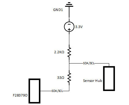
For the F28379D LaunchPad I can read the data properly for the MPU-9150 sensor present on BOOSTXL-SENSHUB only when I connect 33 ohm series resistor between master and slave pins as shown in the below image. But this is not required when I use other LaunchPads or ControlCards.
Can you help me out on this? Why do i face the problems with F28379D LaunchPad and why I need the series resistor between Master and Slave pins to make I2C work?
Thanks,
Aditya


