This thread has been locked.
If you have a related question, please click the "Ask a related question" button in the top right corner. The newly created question will be automatically linked to this question.
Hi,
I have a 3 phase PFC application. I measure 3 phase currents, 3 phase voltages, dc voltage and dc current. The 3 phase voltages are "smooth" 50Hz, the 3 phase currents have high frequency ripple on them and dc voltage/current are also smooth and slow changing.
For measuring hardware I have: 5x AMC1303E2520: Manchester coded internal clk (for phase voltages and dc) and 3x AMC1306E25: Manchester coded externally clocked together by 20 MHz oscilator(for phase current). This is so that the current that has a high rate of change is sampled together and is totally synchronised.
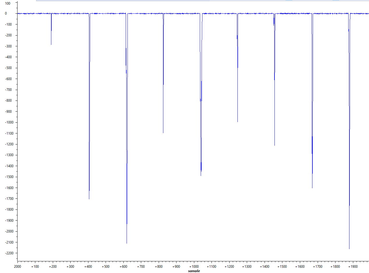
I have used SDFM + AMC1303E2520 on a previews project without problems, but now I have problems with getting correct data. I have an interrupt set (like in examples) and I just read the data and save it. I'm measuring nothing (but I have resistors - shunt and voltage ladder connected) so I would expect to constantly measure 0+/-some noise.
And for voltage I get something like that. But for current I get spikes every now and then. They are both on SDFM1 module, configured the same. As seen in attacked pictures. On the picture is IL1 and UL1. The same exact situation is for other phase currents and voltages.
Any ideas why?
MarkoAnte,
Can you please clarify if my understanding is correct?
1) 3-phase voltage measurement uses AMC1303E2520 modulator:
- 50Hz signal
- No problem with SDFM results
2) DC voltage measurement uses AMC1303E2520 modulator:
- No problem with SDFM results
3) DC current measurement uses AMC1303E2520 modulator:
- No problem with SDFM results
4) 3-phase current measurement uses AMC1306E25 modulator:
- Spurious erroneous filter results
- 3 phase currents have high frequency ripple on them
I also want you to elaborate on the high frequency ripple noise on 3 phase current? Are you saying your seeing high frequency noise coupled on the manchester input bit stream?
Regards,
Manoj
Hi,
for additional clarification on the flags. I have the program, in interrupt, now like this:
...
DELAY_US(1); FlagRegister = Sdfm_readFlagRegister(SDFM1); FlagRegisterstart = FlagRegister; if(CHECK_BIT(FlagRegister, 12)){
//read data here Sdfm_clearFlagRegister(SDFM1, SET_BIT(temp, 12)); } if(CHECK_BIT(FlagRegister, 13)){
//read data here Sdfm_clearFlagRegister(SDFM1, SET_BIT(temp, 13)); } if(CHECK_BIT(FlagRegister, 14)){
//read data here Sdfm_clearFlagRegister(SDFM1, SET_BIT(temp, 14)); } if(CHECK_BIT(FlagRegister, 15)){
//read data here Sdfm_clearFlagRegister(SDFM1, SET_BIT(temp, 15)); } Sdfm_clearFlagRegister(SDFM1,0x80000000); FlagRegisterend = Sdfm_readFlagRegister(SDFM1); --> brake point here
When I stop at the break point I usually have something like:
FlagRegisterstart = 0x8000F000
FlagRegisterend = 0x80008000
Right now I'm not even trying to read the data.
The same happens if I run the code with out the DELAY_US(1); -> I wanted to make sure that all the filters set the flag, if there would be some difference of the clk form the internal clocks and the external clock. I also have the modulator failure interrupt enabled.
Best regards,
Marko
So now my program is:
__interrupt void Sdfm1_ISR(void) { LED_2_PIN_TOGGLE(); Sdfm_clearFlagRegister(SDFM1,0x8000F000); PieCtrlRegs.PIEACK.all = PIEACK_GROUP5; }
and I only have one interrupt configured at a time. One for one AMC1306E25 and one for one AMC1303E2520. I measured the toggling led with a scope.
For AMC1303E2520 I had to set up a pass fail mask. I get 1 fail every 50000 - 70000 oscilloscope measurements. The sample rate seems to drop for 8 or so samples and then get back to normal. See picture:
The AMC1306E25 is so much worse that I had to set up an measurement with persistence on screen for 100ms because the pass/fail mask would always trigger when I pressed start. As seen here, there is a lot of jitter:
For refferance this is how the AMC1303E2520 looked:
Why would the sample rate drop on the AMC1303E2520 and why would the AMC1306E25 be so jittery? For oscilator I'm using a 50 ppm oscilator with phase and period jitter in the ps range.
HI,
no I'm not using the pwm for sync.
In my last post you can see that I'm triggering on a single filter interrupt and I'm not even reading the data and something is obviously wrong.
Best regards,
Marko
So I changed all my modulators for AMC1303E2520 ones. At first glance the problem was solved as there was no more heavy jitter on the sample time. But after some more testing I found out that the problem is still here.
And now I'm totally confused/lost. I set up a test program like this:
//pin set up //SDFM1 GPIO_SetupPinOptions(48, GPIO_INPUT, GPIO_ASYNC); GPIO_SetupPinMux(48,GPIO_MUX_CPU1,7); GPIO_SetupPinOptions(50, GPIO_INPUT, GPIO_ASYNC); GPIO_SetupPinMux(50,GPIO_MUX_CPU1,7); GPIO_SetupPinOptions(52, GPIO_INPUT, GPIO_ASYNC); GPIO_SetupPinMux(52,GPIO_MUX_CPU1,7); GPIO_SetupPinOptions(54, GPIO_INPUT, GPIO_ASYNC); GPIO_SetupPinMux(54,GPIO_MUX_CPU1,7); //SDFM2 GPIO_SetupPinOptions(56, GPIO_INPUT, GPIO_ASYNC); GPIO_SetupPinMux(56,GPIO_MUX_CPU1,7); GPIO_SetupPinOptions(58, GPIO_INPUT, GPIO_ASYNC); GPIO_SetupPinMux(58,GPIO_MUX_CPU1,7); GPIO_SetupPinOptions(60, GPIO_INPUT, GPIO_ASYNC); GPIO_SetupPinMux(60,GPIO_MUX_CPU1,7); GPIO_SetupPinOptions(62, GPIO_INPUT, GPIO_ASYNC); GPIO_SetupPinMux(62,GPIO_MUX_CPU1,7); //sdfm set up //nastavi mode inputov za SDFM filtre Sdfm_configureInputCtrl(SDFM1, FILTER1, MODE_2); Sdfm_configureInputCtrl(SDFM1, FILTER2, MODE_2); Sdfm_configureInputCtrl(SDFM1, FILTER3, MODE_2); Sdfm_configureInputCtrl(SDFM1, FILTER4, MODE_2); Sdfm_configureInputCtrl(SDFM2, FILTER1, MODE_2); Sdfm_configureInputCtrl(SDFM2, FILTER2, MODE_2); Sdfm_configureInputCtrl(SDFM2, FILTER3, MODE_2); Sdfm_configureInputCtrl(SDFM2, FILTER4, MODE_2); //nastavi filtre za uporabo pri comparatorju Sdfm_configureComparator(SDFM1, FILTER1, SINC2, OSR_32, 0, 0x7FFF); Sdfm_configureComparator(SDFM1, FILTER2, SINC2, OSR_32, 0, 0x7FFF); Sdfm_configureComparator(SDFM1, FILTER3, SINC2, OSR_32, 0, 0x7FFF); Sdfm_configureComparator(SDFM1, FILTER4, SINC2, OSR_32, 0, 0x7FFF); Sdfm_configureComparator(SDFM2, FILTER1, SINC2, OSR_32, 0, 0x7FFF); Sdfm_configureComparator(SDFM2, FILTER2, SINC2, OSR_32, 0, 0x7FFF); Sdfm_configureComparator(SDFM2, FILTER3, SINC2, OSR_32, 0, 0x7FFF); Sdfm_configureComparator(SDFM2, FILTER4, SINC2, OSR_32, 0, 0x7FFF); //nastavi filtre za glavne podatke Sdfm_configureData_filter(SDFM1, FILTER1, FILTER_ENABLE, SINC2, OSR_64, DATA_16_BIT, SHIFT_0_BITS); Sdfm_configureData_filter(SDFM1, FILTER2, FILTER_ENABLE, SINC2, OSR_64, DATA_16_BIT, SHIFT_0_BITS); Sdfm_configureData_filter(SDFM1, FILTER3, FILTER_ENABLE, SINC2, OSR_64, DATA_16_BIT, SHIFT_0_BITS); Sdfm_configureData_filter(SDFM1, FILTER4, FILTER_ENABLE, SINC2, OSR_64, DATA_16_BIT, SHIFT_0_BITS); Sdfm_configureData_filter(SDFM2, FILTER1, FILTER_ENABLE, SINC2, OSR_64, DATA_16_BIT, SHIFT_0_BITS); Sdfm_configureData_filter(SDFM2, FILTER2, FILTER_ENABLE, SINC2, OSR_64, DATA_16_BIT, SHIFT_0_BITS); Sdfm_configureData_filter(SDFM2, FILTER3, FILTER_ENABLE, SINC2, OSR_64, DATA_16_BIT, SHIFT_0_BITS); Sdfm_configureData_filter(SDFM2, FILTER4, FILTER_ENABLE, SINC2, OSR_64, DATA_16_BIT, SHIFT_0_BITS); //dissable externe resete Sdfm_configureExternalreset(SDFM1,0,0,0,0); Sdfm_configureExternalreset(SDFM2,0,0,0,0); //Nastavi interrupte samo za modulation failer in za novo dato Sdfm_configureInterrupt(SDFM1, FILTER1, IEH_DISABLE, IEL_DISABLE, 0, 0); Sdfm_configureInterrupt(SDFM1, FILTER2, IEH_DISABLE, IEL_DISABLE, 0, 0); Sdfm_configureInterrupt(SDFM1, FILTER3, IEH_DISABLE, IEL_DISABLE, 0, 0); Sdfm_configureInterrupt(SDFM1, FILTER4, IEH_DISABLE, IEL_DISABLE, 0, 0); Sdfm_configureInterrupt(SDFM2, FILTER1, IEH_DISABLE, IEL_DISABLE, MFIE_DISABLE, 0); Sdfm_configureInterrupt(SDFM2, FILTER2, IEH_DISABLE, IEL_DISABLE, MFIE_DISABLE, 0); Sdfm_configureInterrupt(SDFM2, FILTER3, IEH_DISABLE, IEL_DISABLE, MFIE_DISABLE, 0); Sdfm_configureInterrupt(SDFM2, FILTER4, IEH_DISABLE, IEL_DISABLE, MFIE_DISABLE, 0); DELAY_US(100); //enable glavni filter Sdfm_enableMFE(SDFM1); Sdfm_enableMFE(SDFM2); //Master interrupt enable za ta modul Sdfm_enableMIE(SDFM1); Sdfm_enableMIE(SDFM2); //and iterrupt __interrupt void Sdfm1_ISR(void) { Uint32 FlagRegister; LED_0_PIN_TOGGLE(); FlagRegister = Sdfm_readFlagRegister(SDFM1); if(FlagRegister & 0x00001000){ U31[i1] = SDFM1_READ_FILTER1_DATA_16BIT; if(U31[i1] > max){ max = U31[i1]; LED_7_PIN_TOGGLE(); } else if(U31[i1] < min){ min = U31[i1]; LED_7_PIN_TOGGLE(); } if(i1 < 2000){ i1++; } Sdfm_clearFlagRegister(SDFM1, 0x00001000); } if(FlagRegister & 0x00002000){ IL3[i2] = SDFM1_READ_FILTER2_DATA_16BIT; if(IL3[i2] > max){ max = IL3[i2]; LED_7_PIN_TOGGLE(); } else if(IL3[i2] < min){ min = IL3[i2]; LED_7_PIN_TOGGLE(); } if(i2 < 2000){ i2++; } Sdfm_clearFlagRegister(SDFM1, 0x00002000); } if(FlagRegister & 0x00004000){ U23[i3] = SDFM1_READ_FILTER3_DATA_16BIT; if(U23[i3] > max){ max = U23[i3]; LED_7_PIN_TOGGLE(); } else if(U23[i3] < min){ min = U23[i3]; LED_7_PIN_TOGGLE(); } if(i3 < 2000){ i3++; } Sdfm_clearFlagRegister(SDFM1, 0x00004000); } if(FlagRegister & 0x00008000){ IL2[i4] = SDFM1_READ_FILTER4_DATA_16BIT; if(IL2[i4] > max){ max = IL2[i4]; LED_7_PIN_TOGGLE(); } else if(IL2[i4] < min){ min = IL2[i4]; LED_7_PIN_TOGGLE(); } if(i4 < 2000){ i4++; } Sdfm_clearFlagRegister(SDFM1, 0x00008000); } Sdfm_clearFlagRegister(SDFM1,0x80000000); //Sdfm_clearFlagRegister(SDFM1,0x8000F000); PieCtrlRegs.PIEACK.all = PIEACK_GROUP5; } __interrupt void Sdfm2_ISR(void) { Uint32 FlagRegister; FlagRegister = Sdfm_readFlagRegister(SDFM2); LED_0_PIN_TOGGLE(); if(FlagRegister & 0x00001000){ U12[i11] = SDFM2_READ_FILTER1_DATA_16BIT; if(U12[i11] > max){ max = U12[i11]; LED_7_PIN_TOGGLE(); } else if(U12[i11] < min){ min = U12[i11]; LED_7_PIN_TOGGLE(); } if(i11 < 2000){ i11++; } Sdfm_clearFlagRegister(SDFM2, 0x00001000); } if(FlagRegister & 0x00002000){ IL1[i12] = SDFM2_READ_FILTER2_DATA_16BIT; if(IL1[i12] > max){ max = IL1[i12]; LED_7_PIN_TOGGLE(); } else if(IL1[i12] < min){ min = IL1[i12]; LED_7_PIN_TOGGLE(); } if(i12 < 2000){ i12++; } Sdfm_clearFlagRegister(SDFM2, 0x00002000); } if(FlagRegister & 0x00004000){ Udc[i13] = SDFM2_READ_FILTER3_DATA_16BIT; if(Udc[i13] > max){ max = Udc[i13]; LED_7_PIN_TOGGLE(); } else if(Udc[i13] < min){ min = Udc[i13]; LED_7_PIN_TOGGLE(); } if(i13 < 2000){ i13++; } Sdfm_clearFlagRegister(SDFM2, 0x00004000); } if(FlagRegister & 0x00008000){ Idc[i14] = SDFM2_READ_FILTER4_DATA_16BIT; if(Idc[i14] > max){ max = Idc[i14]; LED_7_PIN_TOGGLE(); } else if(Idc[i14] < min){ min = Idc[i14]; LED_7_PIN_TOGGLE(); } if(i14 < 2000){ i14++; } Sdfm_clearFlagRegister(SDFM2, 0x00008000); } Sdfm_clearFlagRegister(SDFM2,0x80000000); PieCtrlRegs.PIEACK.all = PIEACK_GROUP5; }
Basically I set up 1 led to toggle for each interrupt of a single filter and set up another led to toggle when there was another max/min value.
I got these results:
Filter | What I'm measuring | min/max | dropped samples (lower sample frequency) |
SDFM1_F1 | U31 | -4096/4096 | yes |
SDFM1_F2 | IL3 | -4/4 | no |
SDFM1_F3 | U23 | -224/4 | no |
SDFM1_F4 | IL2 | -4096/4096 | yes |
SDFM2_F1 | U12 | -4/4 | no |
SDFM2_F2 | IL1 | -4096/4096 | yes |
SDFM2_F3 | Udc | -408/4 | no |
SDFM2_F4 | Idc | -4096/4096 | yes |
observed then when the sample rate drops for those couple of samples I get +/- saturation. Some channels are fine like IL3 and U12, but 2 also have some strange noise on them.
All these measurement channels are the same now. Same chip and same layout, same schematic. They were all made as hierarchy blocks, so I copy and pasted them in layout.
Also what I found extremely strange is that I also recorded the bit streams of modulators. When the pin toggled saying that I have a new min max there was nothing strange. As far as I get it sigma delta bit stream average is the value for that sample. And for something like 4096 I would exact to see all 1 or close to it. But all I saw was a bit stream of constant frequency and was like
101010101010101100101010101010
and here ^(where there are 1100)
was where the first wrong data came in
I then also tested the chips with no clock and compared the data streams.
I got something like:
no internal clock: 0011101001100110100110011001101001100110011010011
w/ internal clock: 011001010101011001010101010110010101010101010101100
Both chips had basically average of 0.5. But one when 0101 for the most time and the other when 0011 for the most time.
I don't know. Maybe the problem is with the MCU after all - almost like it does not like 1100 :)
I have no idea what to think.
Best regards,
Marko
I enable one at a time with debugger, so I'm 100% sure that I'm reading correct filter results.
My inputs are all connected to resistors - circuit are like are shown in the datasheet (figure 55 page 29 and figure 57 page 31). So in the case of eg. SDFM1_F4 both analog pins are connected to ground via the 0.01 Ohm resistor + the 330 ohm resistors marked R_flt (Figure 58, page 32). But I also have tired to solder bridge pins 2,3 and 4. Exact same performance.
How does my bit stream show saturation? As per figure 46 on page 23 saturation would be if I had decoded Manchester to all 0 or all 1. But I just have different patters both averaging out to 0.5 or as analog 0V. Right?
The table I have shown was made by only having 1 filter active at a time and taking a look at the results.
datasheet I'm referring too:
www.ti.com/.../amc1303e2520.pdf
Regards,
Marko
Marko,
This is more SD-modulator question. I will leave that to AMC1303 engineers to answer.
Regards,
Manoj
No the issue is still not resolved.
It look like the MCUs Manchester decoder is not working correctly.
What would cause the MCU to not decode the Manchester coding correctly? I though maybe it is a MCU clock problem. How could I test that? I probed the crystal and it seems to oscillate fine.
If I remade the board and used non Manchester coded chips is there a different mechanisem that samples the data going into the SDFM module?