This thread has been locked.

If you have a related question, please click the "Ask a related question" button in the top right corner. The newly created question will be automatically linked to this question.

Abnormal identification

Other Parts Discussed in Thread: DRV8301-69M-KIT, MOTORWARE, OPA2365

I do my board according to DRV8301-69M-KIT.The only difference is that I use hall sensor  for current sampling.As shown.The measuring range of hall sensor is ± 833.33A.

Now I encounter some problems.The parameters of my BLDC motor can be identified well on DRV8301-69M-KIT,but something unusual happened on my board.The motor produce a strong shock and a harsh noise in lab02a.

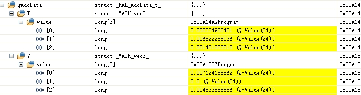
As I know, the current(100Hz) is injected in order to calculate current controller gains in lab02a.So I see waveform of this current.I was shocked the current was too large... As shown

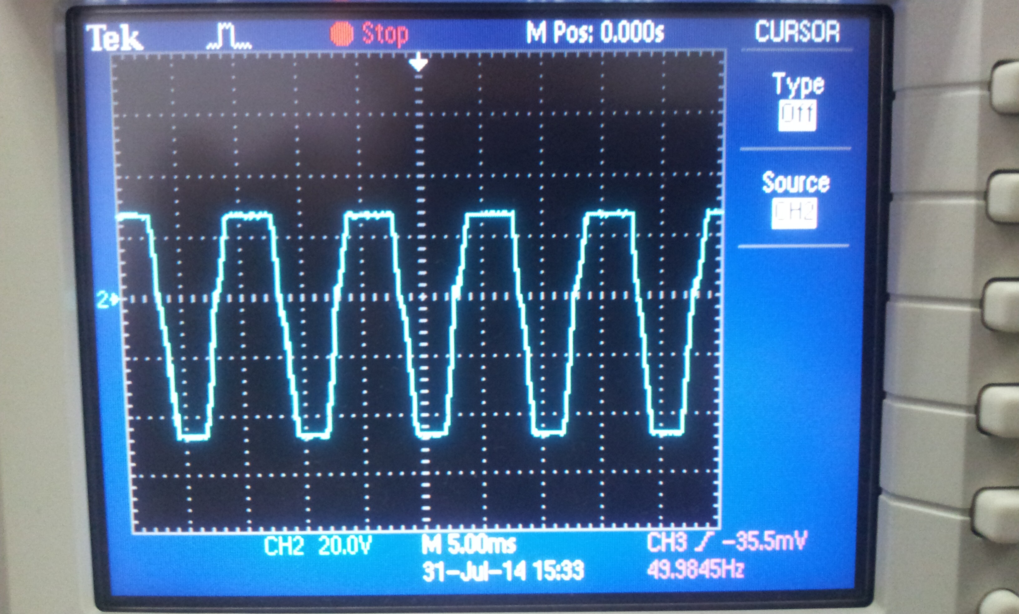
Current frequency is 100Hz,but peak-to-peak value = 74A. I do not know the reason.


My motor parameters:

Maximum speed:1500 rpm

Rated voltage:48V

Pole pairs:4

Rated power: 1KW


motorware:13

CCS:5.5

compiler:6.2.6

user.h:6013.user.h


  • why are you using 833A current sensors for ~20A motors?

    You will have no resolution on your current sensing. This won't be good.

    at a minimum update

    #define USER_IQ_FULL_SCALE_CURRENT_A          (835.0)

    but again, your resolution is going to be absolutely terrible.

    also, did you check the polarity as described in SPRUHJ1 section 5.2.2  ?

    minor item, you should start with this set to your bus voltage

    #define USER_IQ_FULL_SCALE_VOLTAGE_V      (25.0)

    your timing is also incorrect

    #define USER_PWM_FREQ_kHz                (20.0)   // ok

    #define USER_NUM_PWM_TICKS_PER_ISR_TICK        (3)  // this is going to divide the ADC EOC main interrupt down to 6.6666 kHz

    and then you have your speed/traj at /15 of that for 444.444 Hz

    If you want to use (20.0) KHz PWM I would try

    #define USER_NUM_PWM_TICKS_PER_ISR_TICK        (2) // 10 KHz effective main interrupt

    #define USER_NUM_CTRL_TICKS_PER_SPEED_TICK  (10)

    #define USER_NUM_CTRL_TICKS_PER_TRAJ_TICK   (10)

    lastly. this is pretty low for a PM motor

    #define USER_IQ_FULL_SCALE_FREQ_Hz        (110.0)

    with your 4 pole pairs that's only 1650 RPM max. Is that correct?

  • Thanks for your reply.

    why are you using 833A current sensors for ~20A motors?

    I want to design a motor driver which can withstand high current(400A).This motor is used only to test the board. I know the motor is inappropriate about the resolution issue.But I do not think this reason can generate current injected so high.

    also, did you check the polarity as described in SPRUHJ1 section 5.2.2  ?

    If the direction is incorrect,then the Rs value will be negative.But I got a positive number,Did this mean the direction is correct?

    minor item, you should start with this set to your bus voltage

     I made a stupid mistake.But can it make current injected so high?

    your timing is also incorrect

    I will modify parameters about timing as you suggest.

    with your 4 pole pairs that's only 1650 RPM max. Is that correct?

    It is correct.The BLDC motor is only used for test.


    Now I have a new discovery: I can use DRV8301-69M-KIT to do a same issue as my board,when I comment out the code about  ADC(EXT IA-FB、EXT IB-FB and EXT IC-FB).Ashown.

    When I detected the injection current,I got a same waveform as above, Also produce a strong shock and a harsh noise. Then I checked ADC interface map on my own board,but  interface map is correct.

    So I suspect whether software program of InstaSPIN solution is unfit for sampling phase current,and only for shunt resistance or sensors that connect  to transistors which are connected to the GND?

    Do you have any successful cases about  sampling phase current ?


  • I think the main problem was in the IQ_CURRENT vs. ADC_CURRENT.

    Try it set correctly with IQ_CURRENT >= ADC_CURRENT / 2

    chao yang said:

    why are you using 833A current sensors for ~20A motors?

    I want to design a motor driver which can withstand high current(400A).

    I still say this is too wide a current range for 400A system, you are still wasting half the resolution most of the time.

  • I have modified parameters as you suggest,then I run lab02a.But I did not solve the problem.I used current clamp to view C-phase current on my board. The waveform of injected current was the same as before,Current frequency was still 100Hz,peak-to-peak value = 74A,The motor still produce a strong shock and a harsh noise. I didn't find any improvement.

    My new user.h:3817.user.h

    Part of my schematic:7416.Sheet1.PDF

    My control card used TMDSCNCD28069MISO.

    Are these other errors about peripheral hardware circuit ?


  • Now I run lab01 to check ADC pins. 

    EXT_IA_IB  voltage value = 1.657V

    EXT_IB_IB  voltage value = 1.657V

    EXT_IC_IB  voltage value = 1.660V

    I checked the value of gAdcData,as shown

    Is all this case above about ADC normal?

    whether software program of MotorWare is fit for sampling phase current?

  • I think your current sense HW is incorrect

  • Thanks for Chris reply.

    My hall sense is MLX91205. Resolution is 3mV/A.

    See my post before:

    http://e2e.ti.com/support/microcontrollers/c2000/f/902/p/335807/1246504.aspx#1246504

    Do you think there is the wrong design concept about peripheral hardware circuit of opa2365? 


  • Could you swap the polarity of your current sensor? It sounds like a inverse polarity and the current controllers generating maximum voltage trying to compensate a current that grows negative.

  • Thanks Jorge

    I will try to change the polarity of my current sensor to see what will happen and reply here tomorrow.


  • Thanks very much,Chris and Jorge.You are right.

    The polarity of my current sensor is incorrect.Now I have resolved the problem with your help.

    At last,I have a suggestion.we saw so high injected current when the polarity of current sensor is incorrect.I think it is easy to damage a low-power motor.So I think TI can make a fault detection about the polarity of the current sensor by software program.