This thread has been locked.

If you have a related question, please click the "Ask a related question" button in the top right corner. The newly created question will be automatically linked to this question.

TMS320F28335:auto baud function doesn't work

Part Number: TMS320F28335
Other Parts Discussed in Thread: CONTROLSUITE, C2000WARE

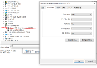
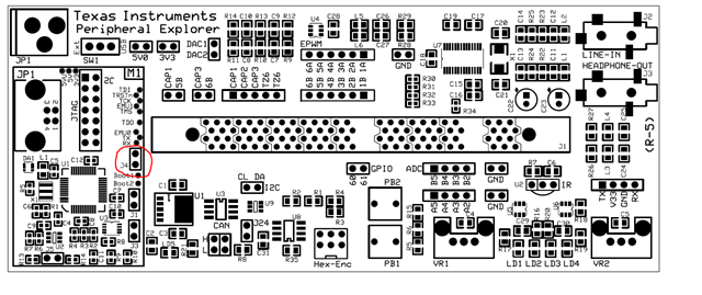
I'm using "TMDSPREX28335 C2000 Peripheral Explorer Kit", but the auto baud function doesn't work.
You can make a normal serial response, but even if you send an "A" serially, there is no response.

The above problem occurred while executing Lab15_1 of the attached disc.
The software matches the provided "Lab15.c".

  • Enomoto,

    Thanks for reaching out to the E2E forum.  Is it possible to verify the COM channel of the PREX board in Device Manager after you have powered it up in SCI Boot config?  I'd like to make sure Windows is detecting and we are  using the correct COM port in whatever Hyperterm type program you are using.

    Best,

    Matthew

  • After closing J3 and configuring SCI boot, I checked the COM port settings.
    As shown in the attached image, the settings are as described in the manual.

  • Enomoto,

    I'm still looking into this, understanding the Boot ROM source.  I should be able to give an update no later than tomm US time.

    Best,

    Matthew

  • Thank you for your reply.

    In reference, my code is below.
    The intent of this code is to boot the binary counter with SCIboot.

    #include "DSP2833x_Device.h"
    
    // Prototype statements for functions found within this file.
    extern void InitSysCtrl(void);
    extern void InitPieCtrl(void);
    extern void InitPieVectTable(void);
    extern void InitCpuTimers(void);
    extern void ConfigCpuTimer(struct CPUTIMER_VARS *, float, float);
    
    
    // Prototype statements for functions found within this file.
    void Gpio_select(void);
    interrupt void cpu_timer0_isr(void);
    
    //###########################################################################
    //						main code									
    //###########################################################################
    void main(void)
    {
    	int counter=0;		// binary counter for digital output
    
    	InitSysCtrl();	 	// Basic Core Initialization
    
    	EALLOW;
       	SysCtrlRegs.WDCR= 0x00AF;	// Re-enable the watchdog 
       	EDIS;			// 0x00AF  to NOT disable the Watchdog, Prescaler = 64
    
    	DINT;				// Disable all interrupts
    	
    	Gpio_select();		// GPIO9, GPIO11, GPIO34 and GPIO49 as output
    					    // to 4 LEDs at Peripheral Explorer)
    
    	InitPieCtrl();		// basic setup of PIE table; from DSP2833x_PieCtrl.c
    	
    	InitPieVectTable();	// default ISR's in PIE
    
    	EALLOW;
    	PieVectTable.TINT0 = &cpu_timer0_isr;
    	EDIS;
    
    	InitCpuTimers();	// basic setup CPU Timer0, 1 and 2
    
    	ConfigCpuTimer(&CpuTimer0,150,100000);
    
    	PieCtrlRegs.PIEIER1.bit.INTx7 = 1;
    
    	IER |=1;
    
    	EINT;
    	ERTM;
    
        CpuTimer0Regs.TCR.bit.TSS = 0;
    
    	while(1)
    	{   
    		while(CpuTimer0.InterruptCount < 10)
    		{
    			EALLOW;
    			SysCtrlRegs.WDKEY = 0x55; // service WD #1
    			EDIS;
    		}
    		CpuTimer0.InterruptCount = 0;
    
      		counter++;
    		// if bit 0 of counter = 1, set GPIO9 to 1
    		if ( counter & 0x00000001 )
    		{
                GpioDataRegs.GPASET.bit.GPIO9 = 1;
            }
            else
            {
                GpioDataRegs.GPACLEAR.bit.GPIO9 = 1;
    		}
    		// if bit 1 of counter = 1, set GPIO11 to 1 
    		if ( counter & 0x00000002 )
    		{
                GpioDataRegs.GPASET.bit.GPIO11 = 1;
            }
            else
            {
                GpioDataRegs.GPACLEAR.bit.GPIO11 = 1;
    		}
    		// if bit 2 of counter = 1, set GPIO34 to 1
    		if ( counter & 0x00000004 )
    		{
                GpioDataRegs.GPBSET.bit.GPIO34 = 1;
            }
            else
            {
                GpioDataRegs.GPBCLEAR.bit.GPIO34 = 1;
    		}
    		// if bit 3 of counter = 1, set GPIO49 to 1 
    		if ( counter & 0x00000008 )
    		{
                GpioDataRegs.GPBSET.bit.GPIO49 = 1;
            }
            else
            {
                GpioDataRegs.GPBCLEAR.bit.GPIO49 = 1;
    		}
    		
    	}
    } 
    
    void Gpio_select(void)
    {
    	EALLOW;
    	GpioCtrlRegs.GPAMUX1.all = 0;		// GPIO15 ... GPIO0 = General Puropse I/O
    	GpioCtrlRegs.GPAMUX2.all = 0;		// GPIO31 ... GPIO16 = General Purpose I/O
    	GpioCtrlRegs.GPBMUX1.all = 0;		// GPIO47 ... GPIO32 = General Purpose I/O
    	GpioCtrlRegs.GPBMUX2.all = 0;		// GPIO63 ... GPIO48 = General Purpose I/O
    	GpioCtrlRegs.GPCMUX1.all = 0;		// GPIO79 ... GPIO64 = General Purpose I/O
    	GpioCtrlRegs.GPCMUX2.all = 0;		// GPIO87 ... GPIO80 = General Purpose I/O
    	 
    	GpioCtrlRegs.GPADIR.all = 0;
    	GpioCtrlRegs.GPADIR.bit.GPIO9 = 1;	// peripheral explorer: LED LD1 at GPIO9
    	GpioCtrlRegs.GPADIR.bit.GPIO11 = 1;	// peripheral explorer: LED LD2 at GPIO11
    
    	GpioCtrlRegs.GPBDIR.all = 0;		// GPIO63-32 as inputs
    	GpioCtrlRegs.GPBDIR.bit.GPIO34 = 1;	// peripheral explorer: LED LD3 at GPIO34
    	GpioCtrlRegs.GPBDIR.bit.GPIO49 = 1; // peripheral explorer: LED LD4 at GPIO49
    
    	GpioCtrlRegs.GPCDIR.all = 0;		// GPIO87-64 as inputs
    	EDIS;
    }   
    
    interrupt void cpu_timer0_isr(void)
    {
    	CpuTimer0.InterruptCount++;
    	EALLOW;
    	SysCtrlRegs.WDKEY = 0xAA;	// service WD #2
    	EDIS;
    
    	PieCtrlRegs.PIEACK.all = PIEACK_GROUP1;
    }
    
    //===========================================================================
    // End of SourceCode.
    //===========================================================================
    

  • Enomoto,

    I think there may be some possible contention when using TX/RX on J12. 

    The reason is that TX/RX on J12 come from signals "ISO-TX/RX" from the control card.  These are GPIO28(SCIARX)/GPIO29(SCIATX) that are sent through an isolator/buffer on the control CARD.  However, GPIO28/29 also go directly to the control CARD header unbuffered in another location.

    On the PREX board, the unbuffered version of these signals go into macro "M1" which is the FTDI serial->USB device.   The FTDI is programmed to emulate:

    1)XDS100v2 debug probe via USB connection to PC

    2)USB to UART connected to GPIO28/29.

    So when we are plugged into the USB for debugging we also have this back channel enabled as well.  Since this connection already exists there is no reason to connect to J12 to the PC.  If we are connecting to J12 as well as the regular USB we may be double driving GPIO28/29 from the PC.

    Can you confirm if you leave J12 unconnected, and just the USB connection to the PC if you can see the echoback example work correctly?

    Best,

    Matthew

  • hi, Matthew

    I'm sorry, I couldn't understand the following countermeasures, so please let me know.

    >> Can you confirm if you leave J12 unconnected, and just the USB connection to the PC if you can see the echoback example work correctly?

    Does disconnecting the J12 mean that you don't need to connect pins?
    When I disconnected the pin connection of J12 and checked the TX and RX pins with an oscilloscope, there was no response in both transmission and reception.
    Please point out if there is any misinterpretation.

  • Enomoto,

    Yes, leave J12 unconnected; but still keep the USB connection from the PC to the PREX board.  Based on the schematic the SCI from the C2000 should be connected to the host PC through that path.  I'm assuming you are using the same PC/host for both CCS as well as UART comms.

    Best,

    Matthew

  • Hi, Matthew

    Okay, in that case do I need to change any GPIO settings from the current software?

    So far, there was no response even if J12 was not connected.

    #include "DSP2833x_Device.h"
    
    // Prototype statements for functions found within this file.
    extern void InitSysCtrl(void);
    extern void InitPieCtrl(void);
    extern void InitPieVectTable(void);
    extern void InitCpuTimers(void);
    extern void ConfigCpuTimer(struct CPUTIMER_VARS *, float, float);
    
    
    // Prototype statements for functions found within this file.
    void Gpio_select(void);
    interrupt void cpu_timer0_isr(void);
    
    //###########################################################################
    //						main code									
    //###########################################################################
    void main(void)
    {
    	int counter=0;		// binary counter for digital output
    
    	InitSysCtrl();	 	// Basic Core Initialization
    
    	EALLOW;
       	SysCtrlRegs.WDCR= 0x00AF;	// Re-enable the watchdog 
       	EDIS;			// 0x00AF  to NOT disable the Watchdog, Prescaler = 64
    
    	DINT;				// Disable all interrupts
    	
    	Gpio_select();		// GPIO9, GPIO11, GPIO34 and GPIO49 as output
    					    // to 4 LEDs at Peripheral Explorer)
    
    	InitPieCtrl();		// basic setup of PIE table; from DSP2833x_PieCtrl.c
    	
    	InitPieVectTable();	// default ISR's in PIE
    
    	EALLOW;
    	PieVectTable.TINT0 = &cpu_timer0_isr;
    	EDIS;
    
    	InitCpuTimers();	// basic setup CPU Timer0, 1 and 2
    
    	ConfigCpuTimer(&CpuTimer0,150,100000);
    
    	PieCtrlRegs.PIEIER1.bit.INTx7 = 1;
    
    	IER |=1;
    
    	EINT;
    	ERTM;
    
        CpuTimer0Regs.TCR.bit.TSS = 0;
    
    	while(1)
    	{   
    		while(CpuTimer0.InterruptCount < 10)
    		{
    			EALLOW;
    			SysCtrlRegs.WDKEY = 0x55; // service WD #1
    			EDIS;
    		}
    		CpuTimer0.InterruptCount = 0;
    
      		counter++;
    		// if bit 0 of counter = 1, set GPIO9 to 1
    		if ( counter & 0x00000001 )
    		{
                GpioDataRegs.GPASET.bit.GPIO9 = 1;
            }
            else
            {
                GpioDataRegs.GPACLEAR.bit.GPIO9 = 1;
    		}
    		// if bit 1 of counter = 1, set GPIO11 to 1 
    		if ( counter & 0x00000002 )
    		{
                GpioDataRegs.GPASET.bit.GPIO11 = 1;
            }
            else
            {
                GpioDataRegs.GPACLEAR.bit.GPIO11 = 1;
    		}
    		// if bit 2 of counter = 1, set GPIO34 to 1
    		if ( counter & 0x00000004 )
    		{
                GpioDataRegs.GPBSET.bit.GPIO34 = 1;
            }
            else
            {
                GpioDataRegs.GPBCLEAR.bit.GPIO34 = 1;
    		}
    		// if bit 3 of counter = 1, set GPIO49 to 1 
    		if ( counter & 0x00000008 )
    		{
                GpioDataRegs.GPBSET.bit.GPIO49 = 1;
            }
            else
            {
                GpioDataRegs.GPBCLEAR.bit.GPIO49 = 1;
    		}
    		
    	}
    } 
    
    void Gpio_select(void)
    {
    	EALLOW;
    	GpioCtrlRegs.GPAMUX1.all = 0;		// GPIO15 ... GPIO0 = General Puropse I/O
    	GpioCtrlRegs.GPAMUX2.all = 0;		// GPIO31 ... GPIO16 = General Purpose I/O
    	GpioCtrlRegs.GPBMUX1.all = 0;		// GPIO47 ... GPIO32 = General Purpose I/O
    	GpioCtrlRegs.GPBMUX2.all = 0;		// GPIO63 ... GPIO48 = General Purpose I/O
    	GpioCtrlRegs.GPCMUX1.all = 0;		// GPIO79 ... GPIO64 = General Purpose I/O
    	GpioCtrlRegs.GPCMUX2.all = 0;		// GPIO87 ... GPIO80 = General Purpose I/O
    	 
    	GpioCtrlRegs.GPADIR.all = 0;
    	GpioCtrlRegs.GPADIR.bit.GPIO9 = 1;	// peripheral explorer: LED LD1 at GPIO9
    	GpioCtrlRegs.GPADIR.bit.GPIO11 = 1;	// peripheral explorer: LED LD2 at GPIO11
    
    	GpioCtrlRegs.GPBDIR.all = 0;		// GPIO63-32 as inputs
    	GpioCtrlRegs.GPBDIR.bit.GPIO34 = 1;	// peripheral explorer: LED LD3 at GPIO34
    	GpioCtrlRegs.GPBDIR.bit.GPIO49 = 1; // peripheral explorer: LED LD4 at GPIO49
    
    	GpioCtrlRegs.GPCDIR.all = 0;		// GPIO87-64 as inputs
    	EDIS;
    }   
    
    interrupt void cpu_timer0_isr(void)
    {
    	CpuTimer0.InterruptCount++;
    	EALLOW;
    	SysCtrlRegs.WDKEY = 0xAA;	// service WD #2
    	EDIS;
    
    	PieCtrlRegs.PIEACK.all = PIEACK_GROUP1;
    }
    
    //===========================================================================
    // End of SourceCode.
    //===========================================================================
    

  • Enomoto,

    From your code, can you confirm that you intend to use GPIO9 and GPIO11 as the TX/RX for the UART?  There is a mux selection for SCIB on these channels. 

    However, looking at both the control CARD schematic and PREX schematic I believe on GPIO28/29(SCIATX/RX) are brought either the the M1 macro or the SCI pin header (J12 on the PREX)

    GPIO28/29 with SCIA is what the autobaud example in C2000Ware/ControlSUITE will use by default.

    If you want to use SCIB(or emulate SCI with GPIO bit banging) we will need to account for GPIO9 and GPIO11.  These come to J5 or J7 as ePWM5B/ePWM6B respectfully.

    I'm sorry for the confusion here on my part, but if you could clarify which GPIO pins and the GPIO module you wish to use I think it will help me to understand the final goal.

    Best,
    Matthew

  • hi, Matthew

    GPIO9 / 11 is planned to be used for LED lighting. so that
    "GpioCtrlRegs.GPADIR.bit.GPIO9" and "GpioCtrlRegs.GPADIR.bit.GPIO11" are in the state where the bit is set in the output.

    I intended to use GPIO28 / 29 as SCIA, but I think that the goal I want to achieve is boot boot by SCI, so if SCIB can achieve it, there is no problem with SCIB.

  • Enomoto,

    Thank you for the detail, I understand more clearly now.  For SCI Boot, we are locked into SCIA only, so we will stick to debugging that.

    If you only plug the only USB connector to the PREX board(which will serve as both XDS100 and UART connection to the PC), can you try to run the echoback example in C2000Ware here 

    C:\ti\c2000\C2000Ware_3_04_00_00\device_support\f2833x\examples\sci_echoback

    This will run at 9600 baud and we should be able to see characters echo'd back to the terminal from the C2000.

    I want to make sure we can communicate correctly with this path before we debug the autobaud bootloader.

    Best,

    Matthew

  • hi, Mattew

    I tried running sci_echoback.
    Since the board and PC are connected by USB on port 4, I monitored port 4 with Hercules, but there is no response.

    I tried to verify the operation with CCS
    I'm stuck in the while statement loop below.

    "Example_2833xSci_Echoback.c" line 189
    >> while (SciaRegs.SCIFF RX.bit.RXFFST! = 1)

  • Enomoto,

    I'm not sure why the secondary channel is not enumerating as a UART, since we don't see that channel we can try the pin header J12 connecting these to the PC directly.  Since there is an isolator inline on the PREX I don't think we have to worry about TTL(PC) vs CMOS(MCU).

    Best,

    Matthew

  • hi, Matthew

    I understand that I don't have to worry.
    I'm sorry but I don't know what to try now.

    What should I check by executing "sci_echoback" with the TX / RX pin disconnected?
    Currently, the while loop on line 189 remains stuck.

    I'm sorry I didn't understand because I have little experience.

  • Enomoto,

    I looked at the schematic again, can you confirm that you are placing a jumper on J4 as shown in the attachment?  This is needed to connect the Rx signal to M1.  If you place the J4, try to see if the Windows HW manager detects the UART via the USB connection as we talked before.

    Best,

    Matthew

  • Until now, I didn't make J4 jump.
    I jumped J4 as instructed and ran Echoback.c again. But the result was the same (I'm stuck in a while loop with XRDY = 1)

    Is it possible to confirm the UART detection on the attached device manager screen? I'm not sure how I can say I'm connected ...

  • Enomoto,

    Thank you for the image, the PC is still not seeing the COM port.  I believe this is an issue with how the FTDI device is programmed to be XDS100v1.

    I have attached a ZIP file that has the programmer application "MPROG" along with a new file to add UART backchannel.  Please extract and follow the below instructions:

    -Have the PREX board plugged into the PC and powered

    -Run the MPROG.exe application

    1)Click the "Open Folder Icon" and pick the F28335_CC_XDS100wUART.ept that is in the same director as the MPROG.exe

    2)Click the "Erase all existing devices" button

    3)Click the "Program all existing device" button

    4)You should note the same dialogue as below picture "Programmed Serial Number ..."

    5)Power cycle the PREX board

    -You should now detect a COM port in HW Device manager, XDS100 Class USB Serial Port (COM##)

    Best,

    MatthewXDS100v1_wUART.zip

  • hi, Matthew

    Thanks for the detailed steps.
    MProg.exe has been executed.
    "Programmed Serial Number ..." doesn't match Mr. Matthew's, is that a problem?

    When I check the device manager, the display is different from the previous one. Can this take me to the next step?


  • Enomoto,

    Its not an issue if the serial number is different, that is OK.  Yes, please try to use the COM6 and see if this will communicate via UART.

    If this does not work, please take a look at this post, regarding a potential fix for a bad driver. https://e2e.ti.com/support/tools/code-composer-studio-group/ccs/f/code-composer-studio-forum/522774/xds100v1-and-xds100v2-driver-problem 

    Best,

    Matthew

  • hi, Matthew

    I tried sending an "A" again using COM6, but there was no response.
    Also, I tried to run "Example_2833xSci_Echoback.c", but it got stuck in the while loop on line 189 as before.
    >> while (SciaRegs.SCIFF RX.bit.RXFFST! = 1)

    I tried to install the driver that was in the proposed case 522774, but there is no progress from the above situation.

    Am I doing something wrong?
    Also, if you have any information that should be presented, please let us know.


    I'm sorry to have taken a lot of time.
    Please help me a little more

  • Enomoto,

    Yes, for some reason the host PC is not recognizing the UART channel on the FTDI device.  I'm assuming this is still caused by some driver issue, but that may be challenging to debug over the E2E.

    Let's remove J4 and attempt to use the single pin header with TX/V33/GND/RX you see at the bottom of the PREX board.  Are you able to manually connect thee TX/RX/GND signals to the DB9 header on your PC?

    Best,

    Matthew

  • hi, Matthew

    Should I connect the single pin header to the PC with a USB connection as it was originally?
    I connected and sent A again, but there was no response.

    The port is newly displayed as COM5 in the device manager.

  • Enomoto,
    Would it be possible for you to take a picture of the connection to the pin header, and the cable/connection to your PC?

    Best,
    Matthew

  • Yes, I will attach a photo.

    The first one is the connection with the board,
    The second piece is the connection with the ELECOM connector.

    The connector of ELECOM is connected to the PC with a USB terminal.

    As for other hardware, a jumper is installed on J3 to enable the auto baud function.


  • Enomoto,

    Is it possible to try the SCI_Echoback example in C2000Ware/ControlSUITE?

    Best,

    Matthew

  • Matthew,

    I have ControlSUITE installed, but I haven't used it, so I don't know how to use it. .. ..

    What should I do from this screen?

  • Enomoto,

    If you navigate down the devices tree you should find the F28335 and then examples folder with the echoback example.

    As another thought, could you try and move the green jumper wire to the other side of the yellow wire on the DB9?  Admittedly I always get confused with the signal routing, but I'd like to make sure the issue isn't that the C2000 TX signal(PC RX) isn't on the incorrect pin.  The C2000 RX/PC TX is the middle pin, so that can't be transposed.

    Best,

    Matthew

  • Matthew

    Found examples file, thank you.
    When I was running, I couldn't get out of the while loop on line 126. (XRDY continues to be in the "1" state.)
    What's wrong with this?

    Also, as suggested, I swapped the green and yellow lines just in case, but there was no change.

  • Enomoto,

    Apologies for the delay on my end on this one.  I'm going to ask a few others here at TI if they have seen this kind of behavior before and any possible causes.  Will try and reply back by tomorrow.

    Best,

    Matthew

  • Enomoto,

    I spoke to some others, can you verify that on the controlCARD that switch SW1 is "on"  Apparently there is an additional enable for the SCI Rx path.  We will still need to use the 4 pin header as in the last few emails.

    There is also another tool that we can try to bootload on the SCI channel at this link called C2PROG.  This would eliminate CCS from the equation or loading an echoback type program.

    Best,

    Matthew