Other Parts Discussed in Thread: MSP430FR6041, , MSP430FR5043, MSP430FR5041
Hi Team,
There's an issue from the customer need your help:
Hello, we have used the "msp430fr6043_saph_01.c" and "msp430fr6043_sdhs_01.c" routines in "MSP430FR6043_MSP430FR6041_MSP430FR5043_MSP430FR5041_Code_Examples".
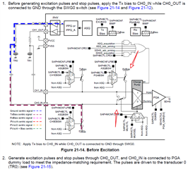
I input a sine wave with a frequency of 1MHz, an amplitude of 300mV, and an offset of 900mV to the CH0_IN pin, as shown in Figure 1. But my original idea was to capture the waveform received by the transducer (yellow waveform in Figure 2). The point where I am confused is because there is a 1000pF capacitor between the signal line of the transducer and the input pin CH0_IN, as shown in Figure 3. So it stands to reason that the waveform received by the transducer (yellow waveform in Figure 2) can be captured without adding a 900mV offset. Put the picture 4 5 6 in the results array when the transducer is connected to try to capture the waveform received by the transducer (yellow waveform in Figure 2). The captured waveforms are different each time. It is suspected that the signal passes through the 1000pF capacitor. (Figure 3) It is caused by no bias when it is input to the MCU CH0_IN. Do you need to change some registers so that CH0_IN can capture signals without adding 900mV (or the range that can be captured is -700mV-+700mV or greater)? How should I do it?
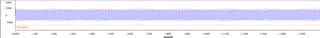
figure 1
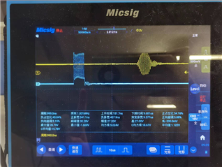
figure 2
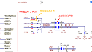
figure 3
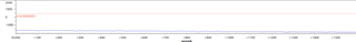
figure 4
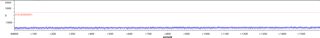
figure 5
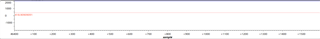
figure 6
I used 8MHz sampling frequency, 1600 sampling points, and turned on sampling in timer2, which is the clock that triggers the emission stimulus. The waveform of CH0_IN can also be observed with an oscilloscope. It stands to reason that the results array completely includes the receiving waveform with a difference of 60us from the excitation signal and a duration of 15us. I have tried all the parameters according to the gain table, but none of them seem to be captured, how can I solve it?
Waveform obtained by modifying the gain.zip
Could you help check this case?
Thanks & Regards,
Ben