This thread has been locked.

If you have a related question, please click the "Ask a related question" button in the top right corner. The newly created question will be automatically linked to this question.

EVM430-FR6047: USS parameter tuning and errors

Part Number: EVM430-FR6047
Other Parts Discussed in Thread: UNIFLASH

Tool/software:

Hello,

I have recently been testing the EVM430FR6047 eval kit on a water flow meter test rig. After calibration with the default values the water meter displays the same values as the reference flowmeter. However, when i attempt to tune parameters it can cause the flowmeter to change from the correct value to  -21124 L/h. 

The only way for me to fix the issue is to reset the device - > update the settings then enter the calibrated meter constant then update the settings again.

If i change parameters such as increasing the number of pulses or changing the gain then i get -21124 L/h again. The GUI feels very temperamental. Some values i have used in the past that worked occasionally do not. 

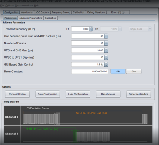
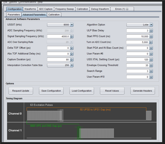
Can anyone help me understand the relationship between the parameters on the configuration tab? 

Any help is appreciated.

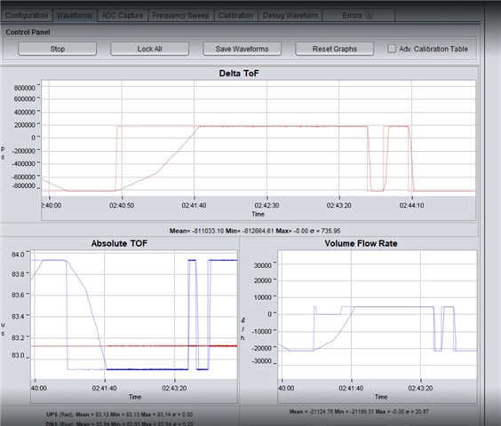
An example of a broken waveform:

  • Hi,

    It seems you are observing a cycle slip issue on the absTOF result. It most probably related to inappropriate envelop crossing threshold setting. Please check on this app note for a better understanding of the USS library. https://www.ti.com/lit/pdf/slaaes9

    Best regards,

    Cash Hao

  • Hi Cash,

    Thanks for getting back to me. I will investigate this parameter next time I have access to the flow meter test rig.

    The most frustrating thing we found was that we would have a working configuration and then change a setting that would cause an error. We would then revert to the original settings and the measurement would remain broken. Can you comment on that? Is there any sequence we should perform to ensure the selected parameters are written to the device? Does it need to be stopped before writing parameter changes?

    Thanks for your help.

  • Hi,

    I assume you are using the USS GUI to update the parameters. If a setting cases an error, it might require to reprogram the MCU again with a good setting to recover it. 

    Best regards,

    Cash Hao

  • Hi Cash,

    Yes, we are using the USS GUI to update the parameters. 

    When we click 'Request update' is that not the same as reprogramming the device?

    To clarify:

    We would have a working configuration, we would then change a parameter, click 'request update' and it would break. We would then change it back to the value that worked previously, again, clicking 'request update' and it would remain broken.

    The only way we were able to fix it was by clicking 'reset values' and re-entering the meter constant.

    Have you experienced this issue before? We would really like to figure out why changing the parameter back to the original value does not fix the issue.

    Is there any sequence we should perform to ensure the selected parameters are written to the device? Does it need to be stopped before writing parameter changes?

    Thanks

  • Hi,

    Click 'Request update' is not reprogramming the device. It just sends the new parameters to the MCU. 

    I have not encounter this issue before, if re-entering the meter constant could solve the issue. Then I suppose that a way for it. 

    Best regards,

    Cash Hao

  • Hi Cash,

    Can you please expand on how to reprogram the device?

    Thanks

  • Hi,

    Just use Uniflash or CCS to program the device again with the default project binary. 

    Best regards,

    Cash Hao

  • Hi Cash,

    OK thanks I can try this next time I have access to a test rig.

    Is it only the envelope crossing threshold parameter that can affect cycle slip? Assuming this is what we are experiencing.

    When we tune parameters should we be able to do it with water flowing through the system? Or should the flow rate be zero? Or should it not matter?

    I have had success with the standard deviation test here Ultrasonic Water Meter - Design and Testing where we fill the flow meter with water and take measurements at 0 flow rate. I did not experience any issues at no flow rate and I was able to tune parameters freely.

    The ADC capture at no flow rate looked like below. 

    Still very interested in trying to figure out the relationship between the problem we have witnessed and tuning the parameters. Is there any data we can log during tests that could help you debug this for us? The problem we have is that we only have infrequent access to the test rig and its very expensive so we need to be prepared with solutions in case we encounter this issue again. 

    Lastly, I was wondering if you could help me understand how important temperature is when measuring flow rate using this system. Do you recommend the calibration type to be 'Flow' or 'Flow + Temperature' ? I read that temperature can improve flow rate accuracies at <100 l/h. On our first set of tests we calibrated solely using 'Flow'.

    Thanks

  • Hi,

    Parameters are usually tuned at zero flow and tested under different flow rate to check if it be set with a proper value. 

    The ADC capture data looks abnormal to me. Have you followed this guide about how to tune parameters? https://dev.ti.com/tirex/explore/node?node=A__AUxLkAvzLrljvLBB0bSqSw__MSP430-ACADEMY__8HaEUeq__LATEST You can also send your configuration page here, I can also check it for you. 

    You do not have a simple flow rate test bench on your side? Usually, cycle slip issue could easily reproduce under simple flow rate test. 

    It depends on your temperature requirement, if your product is designed to work under upto 50 degC and with a good accuracy, than you might need to use Flow + Temperature calibration mode. Otherwise, flow mode should be enough for general application. 

    Best regards,

    Cash Hao

  • Hi Cash,

    OK we can try and reconfigure at zero flow and see if it makes any difference.

    So for the standard deviation test at zero flow i used the parameters in the below screenshots.

    I increased the number of pulses to as many as possible as i read this was the best way to improve SD, i also increased capture duration to 80. I reduced UPS0 to UPS1 gap to 50 so we would take more frequent measurements.  We do not care about power consumption in our application.

    I increased the GAP between pulse start and ADC capture to 80 in order to make the capture more centered on the plot. Then i adjust the Gain so that the ADC counts are about 900. 

    Can you tell me what looks abnormal about it? I would like to try and understand as best as possible how to make the capture as good as possible.

    We might be able to set up something very basic in the office. What sort of flow rates would cycle slip occur at?

    Thanks

    Jonathan

  • Hi,

    It is just that the number of pulses is quite large and makes the receive signal looks abnormal. 

    If you do not care about the power consumption, then I think the current configuration looks good except the GAP between pulse start and ADC capture. You can set it a little shorter incase that the ADC signal moves under flow rate. 

    I do not know at what flow rate would let the cycle slip occur, customer need to test cover the whole designed flow range. 

    Best regards,

    Cash Hao

**Attention** This is a public forum