This thread has been locked.

If you have a related question, please click the "Ask a related question" button in the top right corner. The newly created question will be automatically linked to this question.

Filtering the Acquired analog signal

Other Parts Discussed in Thread: CC430F5137

Hello,

I am acquiring the analog signal using ADC channel at a 500Hz sampling rate using cc430F5137. I am new to digital filters so need guidance with the implementation of Lowpass filter.Can anyone explain how to implement the low pass filter for the obtained values of ADC12MEM0.How the ADC12MEM0 values are to be used or processed,what should be the sampling frequency should be taken if the signal is obtained using a sample rate of 500Hz and if the desired cutoff freq of 3Hz.

Can anyone provide information on the LPfilter implementation and also provide some materials and examples on the implementation method.

Thanks.

  • Perhaps this document will answer your question.

  • The Low Pass Filter example in the document llamas pointed out can be used directly with very little change.

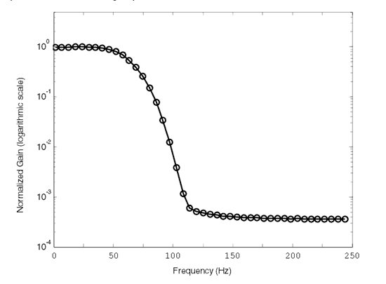
    Since you are using 500 samples/second instead of 4000 samples/second, the plot of the normalized gain on the logarithmic scale versus the frequency will become like this.

  • Hello,

    Can I know how to call the filter function LPF filter.asm after 1 second as I want to apply the lowpass filter  for the collected 500 ADC samples each collected in 2ms.As I want to send the 500 samples to the UART once the LP filtering has been done.

    Thankyou.

  • Could someone explain of how to call the LPF filter.asm function as above described.

  • Filtering is usually an on-going continuos process. You feed an original analog signal to an analog filter circuit and out comes the filtered analog signal. It is continuos in real time with only a small delay called phase shift.

    You can get the same result digitally. You first use ADC to digitize the original analog signal at a fixed rate, apply DSP Filtering to that, and use DAC to produce the filtered analog signal. This is also continuos in real time just like doing it with analog filter circuit.

    Giving that, the DSP Filtering algorithm takes a single digitized original signal as input, and produce a single digital output to be converted to the filtered analog signal. It is designed to be called repeatedly at a fixed sampling rate. Internal to the algorithm, it needs a finite number of old input and/or output. They can be stored locally and not regarded as formal parameters.

    As such, you cannot call that DSP routine with 500 inputs and get 500 outputs at once. But you can call it 500 times. Each time give it one input and get one output in return.

    I may be totally wrong, but it appears to me that someone invisible to us is pulling strings on you. And every time he/she does that, you get all tangled up, start another topic in this forum, and drag us down a slippery slope. This is not helpful and we are not getting anywhere.

  • Hello OCY,

    Really its not happening in the way you are thinking as I am just working myself on a project with different stuffs like analog design and matlab.So,I am modifying the analog device I need and thus thinking in different  ways to test my analog signals in matlab uisng controller from the analog board which are thus leading to the different methods for the microcontroller implementation.Yes,I agree that I posted the two threads related to the filtering but one thread needs a filtering method as metioned here  http://www.ti.com/mcu/docs/litabsmultiplefilelist.tsp?sectionId=96&tabId=1502&literatureNumber=slaa357&docCategoryId=1&familyId=1615

    and other is using the hardware multiplier available on the board.As want to test both of them.

    Thanks.

  • You said you want to calculate average of eight. Did you get that done? How did the gain vs. frequency look like?

    You also said that you used mathlab to design a low-pass filter. What are the filter coefficients? How did the gain vs. frequency look like?

    If there is no one that pulls your strings, then it must be yourself that is pulling our strings to do all sorts of elementary things for you. (Such as changing size of an array from 1000 to 500, divide an integer by 8, and count to 1 second using a 2ms timer.)

  • Sampling at 500 Hz and take "average of eight." gives this frequency response.

  • Hi OCY,
    1)The implementation of eight average used is

    ADC_ISR()
    {
    results[oldest]=ADC12MEM0;
    ADC_sample = results[oldest];
    for (i=0; i < 8; i++)
    ADC_samples[i] = ADC_sample;
    ADC_samples_Avrg = ADC_sample;
    ADC_samples[ADC_samplesPosition++] =results[oldest];
    if (ADC_samplesPosition == 8)
    ADC_samplesPosition = 0;
    ADC_samples_Avrg = 0;
    for (i = 0; i < 8; i++)
    ADC_samples_Avrg += ADC_samples[i];
    ADC_samples_Avrg >>= 3;
    results[oldest]=ADC_samples_Avrg;
    }
    

    This results[oldest] the result of averaging is displayed on terminal.

    2)I designed a BPfilter in matlab using FDA tool with a cutoff of 0.5 to 3Hz  and the filter coefficients obtained are 

    0,0134232916797402
    0,0134232916797402
    0,0133979435180713
    0,0133979435180713
    0,0133735085979440
    0,0133735085979440
    0,0133504664840148
    0,0133504664840148
    0,0133292621498687
    0,0133292621498687
    0,0133102989017309
    0,0133102989017309
    0,0132939324387742
    0,0132939324387742
    0,0132804659926619
    0,0132804659926619
    0,0132701464666348
    0,0132701464666348
    0,0132631614855822
    0,0132631614855822
    0,0132596372715049
    0,0132596372715049
    1
    

    But I don't know how to check the gain Vs frequency response(as in  the  image  you posted above)

    Thanks.

  • stefan 12 said:
    ...

    2)I designed a BPfilter in matlab using FDA tool with a cutoff of 0.5 to 3Hz  and the filter coefficients obtained are 

    0,0134232916797402
    0,0134232916797402
    0,0133979435180713
    0,0133979435180713
    0,0133735085979440
    0,0133735085979440
    0,0133504664840148
    0,0133504664840148
    0,0133292621498687
    0,0133292621498687
    0,0133102989017309
    0,0133102989017309
    0,0132939324387742
    0,0132939324387742
    0,0132804659926619
    0,0132804659926619
    0,0132701464666348
    0,0132701464666348
    0,0132631614855822
    0,0132631614855822
    0,0132596372715049
    0,0132596372715049
    1
    
    ...

    The frequency response of "average of 8" is equivalent to the set of coefficients:

    0.125000
    0.125000
    0.125000
    0.125000
    0.125000
    0.125000
    0.125000
    0.125000

    As you can see, the frequency response of "average of 8" is not very good. I think the coefficients you quoted above is even worse. They drop off too sharply just like the "average of 8". It is not worth the trouble to try it. The Low-pass filter in the TI App Note is much better, but the cutoff frequency is 75 Hz. You need a lot much more nodes to get down to 3 Hz.

  • Hi OCY,

    Thankyou for your guidance for the digital fiters.I am actually developing a Pulse meter so thought of using digital filters for replacing analog filters but now I have other real important things to be implemented on microcontroller so thought its better to use analog filters so as not to make the micrcontroller implementation complicated.So,I am switching to analog filters removing the need for the digital filter implemenation as of now.

  • Here, you can use FIR filter.  Basically FIR filter is convolution of impulse response of system with input signal.

    Or simply it is multiplication of time shifted impulse response and input signal. In this case input signal is nothing but samples in ADC memory Buffer.

    Here is sample code for FIR filter Implementation:

    int16_t ir_filter_display(int16_t sample)

    {
    static int16_t buf[32];
    static int offset = 0;
    int32_t z;
    int i;

    //Filter hard above a few Hertz, using a symmetric FIR. This has benign phase characteristics
    buf[offset] = sample;
    z = mul16(coeffs_dis[11], buf[(offset - 11) & 0x1F]);

    for (i = 0; i < 11; i++)
    z += mul16(coeffs_dis[i], buf[(offset - i) & 0x1F] + buf[(offset - 22 + i) & 0x1F]);

    offset = (offset + 1) & 0x1F;

    return z >> 15;
    }

    Here is link to get coefficients of filter :

    http://arc.id.au/FilterDesign.html

    Here, just fill your parameters and you will get coefficients for required filter.

  • Hi chetan,

    I used the link you posted to desing the LPfilter with fc=2Hz with fs=100Hz ,Mlength=21 and got the filter coefficents.

    Then added the fiter coefficients to the FIR_filter_coeff.dat file  7532.FIR_filter_coeff.dat and generated the FIR_filter.s43 using the FIR_filter_codegen tool and then migrated this FIR_filter.s43 IAR to CCS.

    Later added the FIR_filter.s43(CCS) ,FIR_sine_data.dat,FIR_filter_coeff.dat (I haven't added the Cwrapper file as it only demonstrates the verification of the FIR filter) to my existing project(where it contains the ADC sampling main.c) and it looks like this.

    But how to call the FIR_filter.s43 in the main.c to filter a single ADCsample as you shown in your post and what is this coeffs_dis[11].

    Thanks.

  • Hello,

    Can someone explain how to use the FIR_filter.s43 in the main.c to filter a single ADCsample.

  • You cannot "filter" a single ADC sample. My explanation was sent a long time ago. Here it is again.

    " Filtering is usually an on-going continuous process. You feed an original analog signal to an analog filter circuit and out comes the filtered analog signal. It is continuos in real time with only a small delay called phase shift.

    "You can get the same result digitally. You first use ADC to digitize the original analog signal at a fixed rate, apply DSP Filtering to that, and use DAC to produce the filtered analog signal. This is also continuous in real time just like doing it with analog filter circuit.

    "Giving that, the DSP Filtering algorithm takes a single digitized original signal as input, and produce a single digital output to be converted to the filtered analog signal. It is designed to be called repeatedly at a fixed sampling rate. Internal to the algorithm, it needs a finite number of old input and/or output. They can be stored locally and not regarded as formal parameters.

    "As such, you cannot call that DSP routine with 500 inputs and get 500 outputs at once. But you can call it 500 times. Each time give it one input and get one output in return."


  • Hi OCY,

    you said "As such, you cannot call that DSP routine with 500 inputs and get 500 outputs at once. But you can call it 500 times. Each time give it one input and get one output in return".

    I really don't understand  what this one input and get one output  will refer to in the ADC sampling code.

    Can you explain me how to implement the filtering using FIR_filter.s43 for the ADC sampling code.

    Thankyou.


  • Hi OCY,

    Can you help  me out in filter implementation using FIR_filter.s43 .

    Thankyou.

  • The assembly-coded routine can be called from c program. The prototype is:

    void FIR_filter (int new_data);

    But actually the formal input new_data is ignored and you must pass the actual input in a global variable int input_delay0. The output is returned back in a global variable int output.

    This routine also needs some storage for old input data, they are called input_delay1, input_delay2, input_delay3, etc, They are neither input or output.

    input_delay0 is the one and only input I was talking about. And output is the one and only output I was talking about. Each time your c code calls this FIR_filter(…), you give it one input and you get one output when this routine returns to the caller.

    They provided a c-coded program call wrapper.c 

  • old_cow_yellow said:
    You cannot "filter" a single ADC sample.

    Because single ADC sample would represent static DC voltage at best. Filtering means manipulation of AC signal frequency components, but AC signal is sequence of more than single ADC sample. Filter needs information not only about current sample of signal but also previous samples.

    http://en.wikipedia.org/wiki/Sampling_(signal_processing)

  • Ilmars said:

    You cannot "filter" a single ADC sample.

    Because single ADC sample would represent static DC voltage at best. Filtering means manipulation of AC signal frequency components, but AC signal is sequence of more than single ADC sample. Filter needs information not only about current sample of signal but also previous samples.

    http://en.wikipedia.org/wiki/Sampling_(signal_processing)

    [/quote]

    Exactly!

    Hence the assembly-code routing FIR_filter() cannot do the process of "filter" if you only call it one time. You have to do the ADC at a fixed sampling rate (such as 500 per second) and call FIR_filter() each time you get a new ADC reading. And you have to collect the output of  FIR_filter() each time you call it.

    FIR_filter() takes one input and produces one output at a time. It is not a "filter" by itself, but can be used as part of the "filter" process.

  • Hi,

    I think it can be used like the below in the ADC_ISR

    ADC_sample=ADC12MEM0; 
    results[oldest]=FIR_filter( ADC_sample);


  • Hi OCY, I need your help for the FIR_filter implementation 

    Here are some of your lines that I implemented 

    1)You have to do the ADC at a fixed sampling rate (such as 500 per second)

                      The ADC is being sampled at 500Hz and after this resultis 
                       result=ADC12MEM0;

    2)call FIR_filter() each time you get a new ADC reading.

                       FIR_filter(input_delay0)

    3)And you have to collect the output of  FIR_filter() each time you call it.

    results[oldest]=output;

    Is anything wrong with my above implementation steps because when I tried to see the output on temrianl through UART it is not displaying the filtered samples but they are being displayed when the filter fucntion is not used(I mean direct raw ADC samples)

    As shown below

    extern FIR_filter(int);
    int input_delay0; to int input_delay20;
    int output = 0;
    __interrupt void ADC12ISR(void)
    {
    if (oldest == 499)
    {
    oldest= 0;
    }
    else
    {
    oldest=oldest+1;
    }
    result=ADC12MEM0;//Store ADC12MEM0 value to result(variable)
    results[oldest]=result;
    input_delay0=result;
    FIR_filter(input_delay0);
    results[oldest]=output;// sending the stored 500 samples after 1 sec through UART for termianl display
    __bic_SR_register_on_exit(CPUOFF);
    }

    Can you try to help me out in finding the problem here.


  • Sorry, I cannot help you.

    I do not have the MSP430 chip you are using. I cannot use CCS that you are using. And I do not know what you are doing in the rest of your code. Cut and past together different parts of different working programs usually will not produce a working program unless you know what you are doing. Otherwise you need infinite-monkeys to achieve that. And even if you succeeded in finishing this project, you will still face the same kind of problem for your next project.

    I think you need to step back and learn some basics.

  • Hi OCY,

    I am trying to learn the things and I will explain how I am really doing them.

    I am first figuring out the way in which my sensor output has to be finalized or processed and then trying out find out the ways in which they can be implemented at the microcontroller side.In this process of microcontroller implementation the different steps are

    1)I first started with sampling the sensor output with ADC at a rate of 500HZ and after collecting 500 samples i.e.,1 ADC sample in 2ms (this was solved by you(OCY) at this )

    http://e2e.ti.com/support/microcontrollers/msp430/f/166/p/305049/1065226.aspx#1065226

    2)And after collecting 1 sec duration of signal it was transmitted through UART and displayed on terminal.

    3)then I thought there is a need of low pass filtering the sampled signal as it was having high frequency components. For this one to be implemented I learnt how to implement the digital filtering on microcontroller here

    http://e2e.ti.com/support/microcontrollers/msp430/f/166/t/305798.aspx

     4)And next when I generated the required filter files with my required filter coefficients and migrating from asm to CCS like this 

    I got the filter coeficients using parametrs fa=3Hz,fb=8Hz,lenght=21,Fs=500Hz  in this  http://arc.id.au/FilterDesign.html .

    Then added the fiter coefficients to the FIR_filter_coeff.dat file (file with new coefficients is 0564.FIR_filter_coeff.dat and generated the FIR_filter.s43 using the FIR_filter_codegen tool and then migrated this FIR_filter.s43 IAR to CCS(and it looks  this txt file but with the extension .s43 7446.filter_CCS.txt   .

    Later added the FIR_filter.s43(CCS) ,FIR_sine_data.dat,FIR_filter_coeff.dat to the project where the main.c is sampling the signal at sampling rate of 500Hz.

    5)I came across errors which were solved here

    http://e2e.ti.com/support/microcontrollers/msp430/f/166/p/314114/1095979.aspx#1095979

    6)Finally after removing errors I was not getting the way to make the filter function worked so again needed suggestions to make it work.

    This is the way how I am trying to solve the problems that are coming in my implementation process.

    And I am very sorry if you really feel that I am just copying.

    The main lines of code after following the above steps looks  like this 

    #include <msp430.h>
    extern FIR_filter();
    int input_delay0;
    int input_delay1;
    int input_delay2;
    int input_delay3;
    int input_delay4;
    int input_delay5;
    int input_delay6;
    int input_delay7;
    int input_delay8;
    int input_delay9;
    int input_delay10;
    int input_delay11;
    int input_delay12;
    int input_delay13;
    int input_delay14;
    int input_delay15;
    int input_delay16;
    int input_delay17;
    int input_delay18;
    int input_delay19;
    int input_delay20;
    int output = 0;
    //***UART settings for selecting baudrate***//
    void UART_init(void)
    { 
     }
    //***Converting ADC12MEM0 value to ASCII characters and trasmitting to terminal***//
    void Terminal_display(int Volt)
    {
     }
    int _system_pre_init(void)
    {
     WDTCTL = WDTPW | WDTHOLD;
     return(1);
    }
    void main( void )
    {
     UART_init();//UART function
    //things needed for the ADC sampling
     while (1)
     {
     Terminal_display(results[oldest]);//displaying ADC12MEM0 value on hyperterminal
     ADC12CTL0 |= ADC12SC;//start ADC conversion(after 2ms of timer job)
     __bis_SR_register(CPUOFF + GIE);//CPU OFF mode
     }
    }
    #pragma vector=ADC12_VECTOR
    __interrupt void ADC12ISR(void)
    {
     if (oldest == 499)
     {
     oldest= 0;
     }
     else
     {
     oldest=oldest+1;
     }
     result=ADC12MEM0;//Store ADC12MEM0 value to result(variable)
     input_delay0=result;
     //output=FIR_filter(input_delay0);
     FIR_filter(input_delay0);
     results[oldest]=output;
     __bic_SR_register_on_exit(CPUOFF);
    }
    

  • Hi OCY,

    Is there anything you can help me out with your suggestions for this.

    Thanks.

  • I have tried to help you before, but every single time they end up causing all kinds of problems for you. That is why I stayed out this time.

    When I have time, I will review the tons of posting you generated on this subject and write a source code according to what I know. But I have to forewarn you that it surely will cause CCS to generate lots of error message that you almost surely will not be able to comprehend.

    I do not want to use c to begin with. I would not (and did not) touch CCS with a ten-foot pole. I am limited and I am not a monkey. But you need infinite-monkeys to work for you.

  • stefan 12 said:

    ... I got the filter coeficients using parametrs fa=3Hz,fb=8Hz,lenght=21,Fs=500Hz  in this  http://arc.id.au/FilterDesign.html . ...

    I do not know anything about filter design. But just from common sense, this does not make any sense to me. If Fs=500Hz and length=21, then the FIR filter can only see 21 / 500Hz = 42msec worth of samples. It cannot see one full cycle of any frequency below 1 / 42msec =  28.8Hz. How can it have fa=3Hz and fb=8Hz?

    stefan 12 said:

    ... Then added the fiter coefficients to the FIR_filter_coeff.dat file (file with new coefficients is 0564.FIR_filter_coeff.dat ...

    If I add all the 21 coefficients in that file, I get a total of less than 0.20. So the output of that filter is at most 20% of the input when the frequency is less than 28.8Hz. Is that the kind of Low Pass Filter you want?

    stefan 12 said:

    ... then migrated this FIR_filter.s43 IAR to CCS(and it looks  this txt file but with the extension .s43 7446.filter_CCS.txt ...

    I do not know anything about CCS. But the code in that file looks like it has effectively only one term instead of 21 terms. And the output is always 0.031% of the input at any frequency. (Instead of 20% at low frequency.)

    stefan 12 said:

    ... Later added the FIR_filter.s43(CCS) ,FIR_sine_data.dat,FIR_filter_coeff.dat to the project where the main.c is sampling the signal at sampling rate of 500Hz...

    I do not see why FIR_sine_dat is needed in your project. Nor is FIR_filter coeff.dat.

    stefan 12 said:

    ... 6)Finally after removing errors I was not getting the way to make the filter function work...

    I think CCS can only catch obvious simple trivial mistakes. Your act of "removing errors" is just to satisfy CCS to not generating error messages.

    Aside from what I already pointed out above, I do not understand why your code did not crash. Have you ever test you code to the end of FIR_filter and execute "RET"? Was it called via a "CALL #FIR_filter" or via a  "CALLA #FIR_filter"?

  • Thanks OCY for giving your time for helping me to understand what I am wrong with.

    The lowpass filter designed with Matlab has a length of 104 8 as attached here 5611.FIR_filter_coeff.dat),Fs=500,Fp=3,Fst=8,addition of all coefficients=1.0554 and when it is used to filter the 500 samples(of 1 sec duration) of ADC then it has the following reponse 

    when I tried to generate the same filter(filter length=104 after copying the filter coefficients into FIR_filter_coeff file) with FIR_filter_codegen.exe it is showing error like this 

    I really don't know whether the problem is because of large filter length or anything else.

    The controller I am using has the hardware multiplier so I guess it will be good to make a filter function using the  hardware multiplier instead of using the FIR_filter_codegen.exe tool to generate the assembly FIR_filter_function that actaully need for the controller that don't have hardware multiplier.can you suggest anything about this.

    Thanks.

  • old_cow_yellow said:
    "As such, you cannot call that DSP routine with 500 inputs and get 500 outputs at once. But you can call it 500 times. Each time give it one input and get one output in return."

    Well, that's not quite true. Or rather, it's true for this specific DSP function. And makes sense, since DSP is designed for realtime operation, nut for working on a collected database.
    Of course you can feed the values in the array of 500 inputs one by one and collect the 500 outputs in an array, one by one. Or a 'filter a block of data' function could do it by itself.

    old_cow_yellow said:
    Internal to the algorithm, it needs a finite number of old input and/or output. They can be stored locally and not regarded as formal parameters.

    They could be given as 'seed' parameters, or be reset on each call with a block of data.Or are built by preceding the block whose data is to be filtered with some data that doesn't result in (valid) output values. How many preceding values are required depends on the filter.

    This is why the SD16 requires three conversions whose results are to be discarded, after being switched on or after changing the input channel: the digital filter of the SD16 requires these results to settle.

    However, to draw a picture ofdigital filtering: a very simple low-pass filter can be imagined as a function that gets a value and emits a value that is, if possible, the input value, but differs at most by x from its previous output value). The output of such a simple digital filter function would pretty much match the output of a slew-rate limited analog amplifier.
    I think this example is a good visualization of OCYs "Filtering is usually an on-going continuous process"

**Attention** This is a public forum