


Tool/software: Code Composer Studio
Hi guys,
I'm using the demo "uart_pc_echo_12mhz_brclk.c". I only added a command to the main loop to send a die (0xff) to the UART.

It works, I run the program and I continually receive the value "0xff" on the computer. When I send some data through the computer, and the program enters the interrupt routine of the Rx_UART, it returns the value that I received through the Tx_UART, but does not return to the main routine. It gets stuck in a loop that I do not understand:
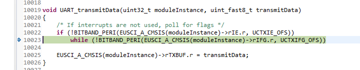
Can someone explain me better why can not go back to the main routine? Am I forgetting some FLAG?
Follow complete code:
/* DriverLib Includes */
#include <ti/devices/msp432p4xx/driverlib/driverlib.h>
/* Standard Includes */
#include <stdint.h>
#include <stdbool.h>
//![Simple UART Config]
/* UART Configuration Parameter. These are the configuration parameters to
* make the eUSCI A UART module to operate with a 9600 baud rate. These
* values were calculated using the online calculator that TI provides
* at:
*software-dl.ti.com/.../index.html
*/
const eUSCI_UART_Config uartConfig =
{
EUSCI_A_UART_CLOCKSOURCE_SMCLK, // SMCLK Clock Source
78, // BRDIV = 78
2, // UCxBRF = 2
0, // UCxBRS = 0
EUSCI_A_UART_NO_PARITY, // No Parity
EUSCI_A_UART_LSB_FIRST, // LSB First
EUSCI_A_UART_ONE_STOP_BIT, // One stop bit
EUSCI_A_UART_MODE, // UART mode
EUSCI_A_UART_OVERSAMPLING_BAUDRATE_GENERATION // Oversampling
};
//![Simple UART Config]
int main(void)
{
/* Halting WDT */
MAP_WDT_A_holdTimer();
/* Selecting P1.2 and P1.3 in UART mode */
MAP_GPIO_setAsPeripheralModuleFunctionInputPin(GPIO_PORT_P1,
GPIO_PIN1 | GPIO_PIN2 | GPIO_PIN3, GPIO_PRIMARY_MODULE_FUNCTION);
/* Setting DCO to 12MHz */
CS_setDCOCenteredFrequency(CS_DCO_FREQUENCY_12);
//![Simple UART Example]
/* Configuring UART Module */
MAP_UART_initModule(EUSCI_A0_BASE, &uartConfig);
/* Enable UART module */
MAP_UART_enableModule(EUSCI_A0_BASE);
/* Enabling interrupts */
MAP_UART_enableInterrupt(EUSCI_A0_BASE, EUSCI_A_UART_RECEIVE_INTERRUPT);
MAP_Interrupt_enableInterrupt(INT_EUSCIA0);
MAP_Interrupt_enableSleepOnIsrExit();
MAP_Interrupt_enableMaster();
//![Simple UART Example]
while(1)
{
MAP_UART_transmitData(EUSCI_A0_BASE, 0xff);
// MAP_PCM_gotoLPM0();
}
}
/* EUSCI A0 UART ISR - Echoes data back to PC host */
void EUSCIA0_IRQHandler(void)
{
uint32_t status = MAP_UART_getEnabledInterruptStatus(EUSCI_A0_BASE);
MAP_UART_clearInterruptFlag(EUSCI_A0_BASE, status);
if(status & EUSCI_A_UART_RECEIVE_INTERRUPT_FLAG)
{
MAP_UART_transmitData(EUSCI_A0_BASE, MAP_UART_receiveData(EUSCI_A0_BASE));
}
}
Any help will be welcome! Thank you.
Let me know if you need more information. I am grateful for your comments.

