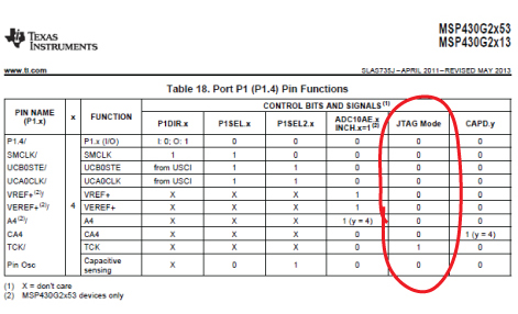
When configuring a port pin to perform a specific function, we use a table from the device's data sheet to learn which which control register bit fields must be set or cleared to enable the function. Shown below is such a table. There is a column in that table called JTAG Mode, and it shows the bits of various functions for the pin.
I'm under the impression that these bits shown in the JTAG Mode column are signals, not control bits that must be set or cleared.
- Is the JTAG Mode Column Showing Control Bits that my firmware must set or clear, or are they just signals?
- Are these actually the signals that appear at the pin when the device is put into JTAG Mode?
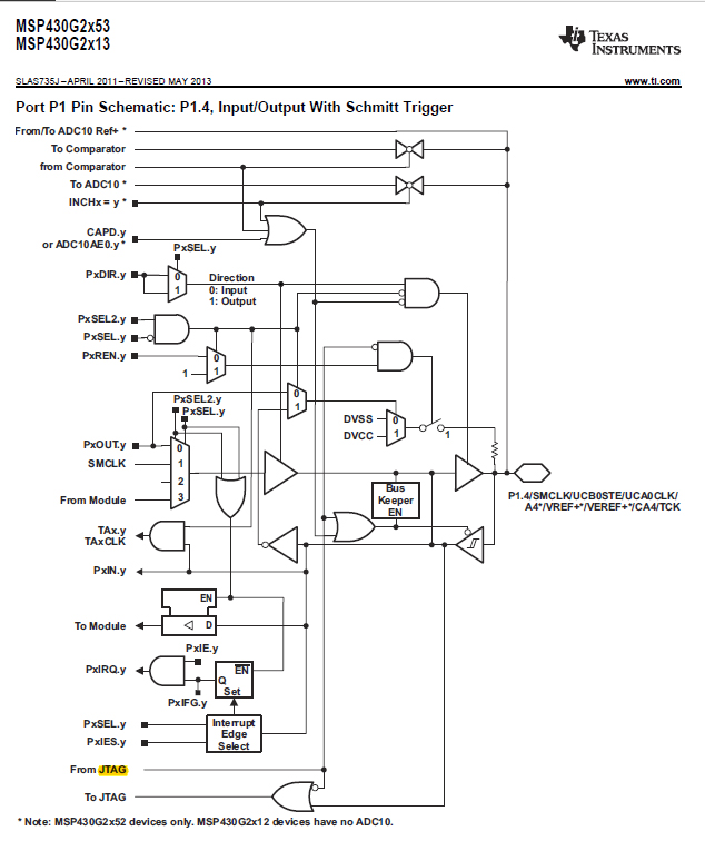
As additional information about this question, here is the corresponding diagram for that pin.