This thread has been locked.

If you have a related question, please click the "Ask a related question" button in the top right corner. The newly created question will be automatically linked to this question.

MSP430: Trouble Reading Memory Block at 0x24400 on Page 0 of Length 0x91: Invalid parameter(s)

Other Parts Discussed in Thread: MSP430F5528

Hello Everybody!

I wrote a little code to read the ADC12 of my MSP430f5528. Here you can see the code:

  ADC12CTL0 = ADC12ON+ADC12MSC+ADC12SHT0_15;    // Turn on ADC12,setze sequenz, set sampling time, 15 ist langsamste
ADC12CTL1 = ADC12SHP+ADC12CONSEQ_3; // Use sampling timer, repeat sequence

ADC12MCTL1 = ADC12INCH_8+ADC12EOS; // channel = A8, end seq., sequenz enthealt nur A8
ADC12IE = 0x02; // Enable ADC12IFG.1, end channel
ADC12CTL0 |= ADC12ENC; // Enable conversions
P5SEL |= 0x01; // P5.0 ADC option select

while (1) {
ADC12CTL0 |= ADC12SC; // Start sampling/conversion

while (!ADC12IFG1); // wait till ready

batterie_spannung = ADC12MEM1;
if (batterie_spannung < 1830){
led4_blink();
}
if (batterie_spannung >= 1830){
led5_blink();
}
}

Stand alone, the code works well, but if I include it in my complete programm I get the follwing error, if I run the code in debug mode:
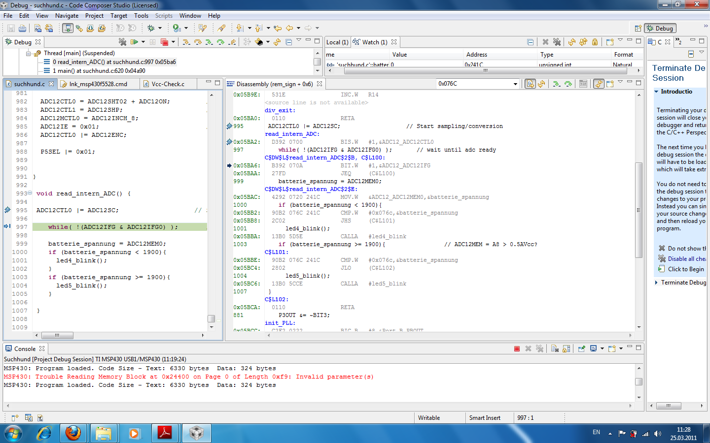
"MSP430: Trouble Reading Memory Block at 0x24400 on Page 0 of Length 0x91: Invalid parameter(s)"
If I run the code anyway, the CPU runs into reset and freezes after it has reached
ADC12CTL0 |= ADC12SC;
which starts the conversion.

The memory mapping should prevent a jump to an address higher than 0x243FF, cause the memory ends here; but it seems that it is not working correct.
The second weired thing is, that the code works well, stand alone.
Has anybody experience with that issue or any suggestions?
I use CCS 4.2.1.00004 .

Thank you very much!

Steve
  • Memory mapping is only logical in the IDE and does not control the physical part.  Thus, you could be jumping to any address an opcode can represent.

    Since there are no #define statements showing what the constants represent, I can only assume they are correct.  I would start there and look to see if there are multiple definitions and which one is active for the invalid build.  If that fails to provide you satisfactory information, try pre-compiling the code and take a look at it after all the preprocessing is complete.  This may reveal what the actual address defined in the code results in.

    Jim Noxon


  • Your wait test is incorrect:

    Stefan Zorn said:
    while (!ADC12IFG1); // wait till ready


    from msp430f5528.h header:

    #define ADC12IFG1              (0x0002)       /* ADC12 Memory 1      Interrupt Flag */

    You should read register and get your flag (this is only one bit):
    while( !(ADC12IFG & ADC12IFG1) );

    Regards,
    Piotr Romaniuk, Ph.D.
    ELESOFTROM

  •  

      You should read register and get your flag (this is only one bit):
    while( !(ADC12IFG & ADC12IFG1) );

    Yes, Piotr you are right. Thank you! I changed my code now like this:

     
    ADC12CTL0 = ADC12SHT02 + ADC12ON; // Sampling time, ADC12 on
    ADC12CTL1 = ADC12SHP; // Use sampling timer
    ADC12MCTL0 = ADC12INCH_8;
    ADC12IE = 0x01; // Enable interrupt
    ADC12CTL0 |= ADC12ENC;

    P5SEL |= 0x01; // P5.0 ADC option select

    while (1) {
    ADC12CTL0 |= ADC12SC; // Start sampling/conversion

    while( !(ADC12IFG & ADC12IFG0) ); // wait until adc ready

    batterie_spannung = ADC12MEM0;
    if (batterie_spannung < 1900){
    led4_blink();
    }
    if (batterie_spannung >= 1900){ // ADC12MEM = A8 > 0.5AVcc?
    led5_blink();
    }
    }

    But this does'nt solve the problem. The error "MSP430: Trouble Reading Memory Block at 0x24400 on Page 0 of Length 0xb1: Invalid parameter(s)" still apears.

    At least I learned a little bit more on how to work with the ADC12. :)

    Any other ideas?

    Best regards

    Steve


  • Can you post screenshot of the CPU core registers contents when the error appear?

    Regards,
    Piotr Romaniuk, Ph.D.
    ELESOFTROM

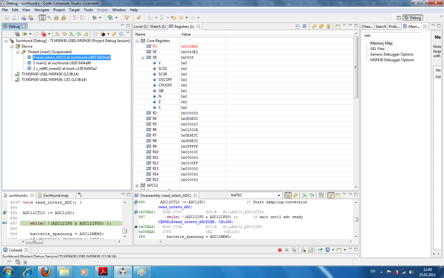
  • I hope this can help you.This is the state  right before the error apears.

    Regrads

    Steve

  • Please enable MCU registers window by:

    View|Registers

    then expand Core Registers (at the top of the window).

    Please make screenshoot of these registers before and after the error.

    You need also to check if you have all interrupt handlers defined for all enabled interrupts, and their vectors are in interrupt vector table (memory 0xFF80-0xFFFF).

    Regards,
    Piotr Romaniuk, Ph.D.
    ELESOFTROM

  • Here you are:

    Before the Error:

    and after:


    thanks a lot!

  • I think that you have interrupt (you have enabled it) and you have not defined its interrupt handler.

    How do you handle ADC12 interrupt that you enable in your code?

    Regards,
    Piotr Romaniuk, Ph.D.
    ELESOFTROM

  • I thought I would need to set the Interrupt to get the right Flag. But I don't. :) When I don't use the

    ADC12IE = 0x01;

    the error does not occur any more!

    Thank you so much!

    But why caused this an error? Is it a problem to enable an interrupt and never use it?

    Again thank you for your help!

    Best regards

    Steve


  • I would like to add link to posts in related thread where this behaviour is explained:

    http://e2e.ti.com/support/microcontrollers/msp43016-bit_ultra-low_power_mcus/f/166/p/100486/354145.aspx#354145

    http://e2e.ti.com/support/microcontrollers/msp43016-bit_ultra-low_power_mcus/f/166/p/100486/354655.aspx#354655

    I think, that the best way to detect such missing vector is setting a breakpoint at address 0xFFFE, if the execution reaches this that vector is missing.

    Regards,
    Piotr Romaniuk, Ph.D.
    ELESOFTROM

  • In very short:

    when you enable particular interrupt, enable global interrupts (GIE bit in SR) and interrupt happens the MCU does not know that you forgot about vector definition.
    MCU continues regular INTR processing: stores PC and SR on the stack and loads interrupt vector from vector table (0xFF80-0xFFFF), dissables interrupts (GIE:=0).

    If you did not define vector it contains 0xFFFF, so PC:=0xFFFE (not 0xFFFF because of required alignment to 2 bytes).

    If you need to write your own interrupt handler (under CCS) you should write something like this:

    #pragma vector= ..here you should write name of the vector - depends on interruot type...
    __interrupt void your_handler(void)
    {
         ...here you can write your code, that will be executed on interrupt...

    }

    For details and template please refer to examples:

    http://focus.ti.com/mcu/docs/mcuflashtools.tsp?sectionId=95&tabId=1538&familyId=342

    Regards,
    Piotr Romaniuk, Ph.D.
    ELESOFTROM

    PS
    I think that the main difference between your embedded and stand alone code were that in this larger one you enabled interrupts,
    so it allows for manifestation of the error.

  • i am using MSP430 G2553 now i want to connect GSM module SIM300 to it and send simple sms to another number pls help me  that i don't know how to code .so please send code to my mail or response in same block 

**Attention** This is a public forum