Because of the holidays, TI E2E™ design support forum responses will be delayed from Dec. 25 through Jan. 2. Thank you for your patience.

This thread has been locked.

If you have a related question, please click the "Ask a related question" button in the top right corner. The newly created question will be automatically linked to this question.

Input impedance of ADC in MSP430F5438

Other Parts Discussed in Thread: MSP430F5438

Hi,

Does anyone know where I can find the value of the input impedance of ADC in MSP430F5438?

I looked through the user guide and specification but no such information was found there.

(I used the multimeter to measure the impedance when MCU was runing a code which made IO pin as ADC input. The value I measured was about 300kohms. It's much smaller than what I thought for an ADC.)

  • Kevin Song said:
    I looked through the user guide and specification but no such information was found there.

    It is there, just not as a simple value.

    There is a statical impedance, which results form the maximum leakage current of 50nA.
    If the voltage is near the trigger level of the digital circuitry, the leakage current may rise to as much as several µA, lowering the statical input impedance to ~400kOhm.I haven't tried, but it might be possible to reduce this by deactivating the GPIO on this port pin by setting the input pins bit in the PxSEL register.

    And then there is a dynamical input impedance:

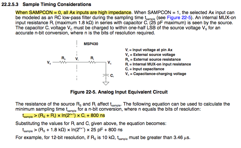
    The ADC12 has a S&H unit, so once the hold stage is entered, the theoretical input impedane is unlimited. But if the sample stage is entered, teh S&H unit draws current to charge teh internal capacitor. This info is found in the ADC description in the users guide. IIRC, it was 12pF with 1kOhm series resistance (but I might be wrong and this value was for the SD16), forming a low-pass during sampling time and significantly lowering the input impedance while the capacitor charges (it increases again the more the capacitor is charged/discharged to the 'final' value)

    Nevertheless, the combined value of 300kOhms sounds reasonable. TI could have place an OpAmp into the input as impedance changer, btu this wuld have increased not only production cost but also had added a significant amount to the current consumption.
    If the low dynamic input impedance is a problem for your applicaiton, you should add an OpAmp to your circuit.

    However, keep in mind that t is a dynamic input mimpedance. So your multimeter is just meaasuring the average. It might be as low as 1kOhm (worst cas) the moment the sampling begins and can rise to several MOhms to the end of the samplign period, giving you 300kOhms in average, but still sampling the voltage as if the impedace had been some MOhms all the time.

  • Hi Jens,

    Thanks for your detailed answer. It's quite helpful for understanding.

    Only one thing is not clear to me. You mentioned "it might be possible to reduce this by deactivating the GPIO on this port pin by setting the input pins bit in the PxSEL register." Do you mean setting PxSEL as 1 or setting PxDIR = 0 here?

  • Kevin Song said:
    Do you mean setting PxSEL as 1

    Yes. I don't have access to my datasheets, but on some MSPs, it latches the digital input and deactivates the input buffer. Depending on implementation, this might reduce the input leakage current, especially the increased current when the input voltage is near the trigger level.
    It's possible but not sure, and on some MSPs, the input buffer is always active, even if the pin is selected for module usage.

    If you try and it really makes a difference, please post it here.

  • Thanks, Jens.

    I check the code and I find it set the PxSEL as 1 when the 300kohms was measured.

    I think the reasons why 300kohms was measured are the charge of the internal capacitor and multimeter meaasures the average like that you explained.

    By ignoring the error of ADC conversion, my colleague calculated the static input impedance (when the internal capacitor is charged fully) from a resistor divider and the ADC raw value. The result is about 8.4Mohms.

    We are ok with the dynamic input impedance and this static input impedance as well.


    The only problem we have now is that we don't know how consistency of this static input impedance is among different chips. We are measuring it.

    Has TI stated any related informaiton?

  • Kevin Song said:
    The result is about 8.4Mohms.

    Sounds good.

    Kevin Song said:
    we don't know how consistency of this static input impedance is among different chips

    The specs tell a maximum leakage current of 50nA, which is 6.6MOhm (on 3.3V) at least. That's all I know of.

  • I recently have a similar inquiry...

    As already discussed here, the data sheet indicates that the input impedance is high.  You also need to make sure that you meet the minimum sampling time.  You configure the sampling time (as a multiple of the ADC12CLK periods) in the ADC12CTL0 register.

    In my case, Rs=5 MOhm, n=12-bit, the calculated sampling time is 1.13us, using the highlighted equation.  Hope that helps.


  • Thanks, Louis.

    This is the factor affecting the dynamic impedance. I've set it according to this equation.

    (By the way, in your case, the 5Mohms should need a sampling time 1.13ms not 1.13us. I think it's just your typo.)

  • Louis said:
     You also need to make sure that you meet the minimum sampling time.

    Indeed. As I said, the input forms a low-pass. And not only a low-pass to the signal on this input , but on the resulting signal when switching inputs. If you only sample one signal, then the minimum sampling time is much smaller, as the capacitor is already pre-charged to the incoming signal and the sampling time can be shorter.

    Louis said:
    In my case, Rs=5 MOhm, n=12-bit, the calculated sampling time is 1.13us, using the highlighted equation.

    As already discovered, it is 1.13ms. For such along sample time, you'll need a timer controlled S&H. Or a slow ADC12CLK, but then the conversion is slow too and the capacitor is discharged more during the slower conversion, leading to a lower precision.

  • "Or a slow ADC12CLK, but then the conversion is slow too and the capacitor is discharged more during the slower conversion, leading to a lower precision."  Agreed.  I am using 32.768KHz sampling clock.  FYI, I took a 1000 samples of a static signal and calculate the sigma which is ~.85mV ( or 3 1/2 lsb).  So 95% of the time we're w/in 7 lsb errors which is sufficient for our application.

  • Louis said:
    I am using 32.768KHz sampling clock.

    so the conversion time is 13/32768 = 400µs. During this time, the voltage on the sampling capacitor may change significantly, causing your error.

    However, sampling one static signal doesn't tell much. You need to sample at least two different voltages. Also, a dynamic error may be cause by the long conversion time as well as by reference error  or othe rfactors.

    If oyu increase the sampling clock (and sample at shorter intervals), does the error decrease?

    Alternatively, you can configure the ADC12 for 10 bit mode, which reduces the conversion time by 2/13 and just eliminates the lowest two bits of your already larger error.

**Attention** This is a public forum