This thread has been locked.

If you have a related question, please click the "Ask a related question" button in the top right corner. The newly created question will be automatically linked to this question.

msp430 bsl_scripter communication error

Other Parts Discussed in Thread: MSP430F5438, MSP430F5418, MSP430F5435, MSP430F5437

Hi everyone, constantly we are getting an error while trying to initialize MSP430F5438 via cp2102. we are using bsl_scripter for initialization of msp430.

Connected pins are shown below:

RXD of CP2102 - TA0.0 (P1.1) of MSP430
TXD of CP2102 - TA0.1 (P1.2) of MSP430
GND & 3.3V of CP2102 - AVcc and Avss of MSP430 (only 2 pins are connected)
DTR of CP2102 - RST pin of MSP430 (with pull-up resistor 47k to 3.3V)
RTS of CP2102 - TEST pin of MSP430

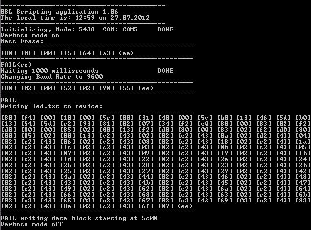
The error shown on the command prompt is shown in the picture:


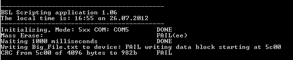
Do we need to connect all the Vcc and Vss pins of MSP430 or just the Avcc and Avss is enough? Do we also need to connect at least one Dvcc and Dvss?

Thanks in advance.

  • Hi.

    if you are using MSP430F5438 (non-A) version, you should choose "543x_family" family instead of "5xx" family. Please refer to the BSL_Scripter_Usage_Guide.

    -----------------------------------------------------------------------------------

    Command Descriptions 

    Command MODE {FAMILY}{COM}

    Description Initializes the selected communication channel for a BSL session and  invokes the BSL (if required). This command also tells the PC side  engine which communication protocol should be used, according to the FAMILY parameter.

    Parameters FAMILY [Required] Acceptable Parameters:
    • 543x_family: Indicates communication with a BSL on the  following devices:
    o MSP430F5418 / MSP4305419
    o MSP430F5435 / MSP4305436
    o MSP430F5437 / MSP4305438
    o Note: the 5438A and all other 54xxA devices are not  included, they are handled by “5xx”
    • 5xx: Indicates communication with all other 5xx
    • 6xx: Currently identical to ‘5xx’ and can be used  interchangeably

    COM [Required] Acceptable Parameters
    • COM{x}: Indicates the PC COM port to use for UART communication, i.e. COM1
    • USB: Indicates that communication will take place via USB

    Examples MODE 543x_family COM1

    MODE 5xx COM1

    MODE 5xx USB

    -----------------------------------------------------------------------------------

    You shall also connect all DVCC to the power supply.

  •               Thanks for reply, we applied your suggestion to our design.

                  When we specify the code as COM5, error repeats itself, but when we changed it as USB (MODE 543x USB), there was no error at all even if nothing was connected to usb of PC. This situation made us a bit suspicious whether the code was loaded or not. 

                 After that, in order to test, we applied a code about blinking a led and at IAR workbench, we generated the code as msp430_txt for bsl format. It is shown below:

    @5C00
    31 40 00 5C 3C 40 00 1C 3D 40 02 00 B0 13 44 5C
    B0 13 18 5C B0 13 56 5C B2 40 80 5A 5C 01 F2 D0
    41 00 05 02 F2 F0 BE 00 03 02 82 93 00 1C FD 27
    F2 E0 41 00 03 02 00 3C 3F 40 33 82 3F 53 FE 2F
    F4 3F 03 43 0F 4C 0F 5D 03 3C CC 43 00 00 1C 53
    0C 9F FB 23 10 01 80 00 5E 5C FF 3F 03 43 80 00
    5A 5C
    @FFFE
    00 5C
    q

    printscreen of bsl :

    we connected the led to P2_0 and nothing happened.

    Could you please give a suggestion for testing and say whether there is a mistake or not in our applications?

  • Hi,

    you should use COM instead of USB, since the F5438 has UART BSL and not USB BSL.

    Have you assigned the correct COM PORT of your cp2102? Maybe for trying whether the cp2102 works, you can try to short the TX and RX pin and play a bit with Hyperterminal to see the echo works.

    Another things, you can try to add VERBOSE in your script file to see the bytes exchanged between BSL_Scripter and the MSP430 target.

    Please refer to the BSL_Scripter_Usage:

    1106.BSL_Scripter_Usage_Guide.pdf

  •      we have already installed COM5 driver and we are expecting of its working but it gives failure all the time. And as you said, we shorted Tx and Rx and we saw the data flow with TERA TERM. So, CP2102 is running properly.

          Another trying is VERBOSE:

    This is the result. However, we still couldnt load anything to MSP430h5438, that is,there is no blinking on led, Now we are getting suspicious of led :))

  • Hi,

    could you try to see how the RST and TEST signal looks like when you execute the BSL_Scripter?

    This will help to understand whether the BSL has been successfully invoked or not.

    Thanks,

  • Hi,

    We tried to see how rst and test pin changed. While BSL_Scripter is running, RST and TEST pins had zero signal. After the process finished, it comes to 3.3V again.

    Previously, we tried to embed the code(from TI website) of  "led blinking" into msp and it did not become succesful and led didn't work. However, this morning when we tried to blink the led by touching it to output pin(P10.7-which normally doesn't give any output), it unexpectedly worked and we are surprised. Now, we are trying to find out how we did it .

    Best Regards

  • Hi Leo,
    We also connected both DSR and DTR pin of CP2102 one by one, while trying to embed the code. Now, when DSR pin of CP2102 is connected, P10.7 gives an output for blinking LED (a square wave signal). When DTR of CP2102 is connected, nothing happened. RST and TEST pins are 3.3Vdc on the scope as Osman Arslan told.

    Thanks.

  • Hi,

    osman arslan said:

    We tried to see how rst and test pin changed. While BSL_Scripter is running, RST and TEST pins had zero signal. After the process finished, it comes to 3.3V again.

    What we need to check is basically whether the BSL Entry Sequence is correctly generated by the CP2102 youa re using. Referring to the SLAU319, the BSL entry sequence should look like this:

    Can you confirm that this kind of waveforms are generated at TEST and RST pins?

    Levent Erb��k said:

    We also connected both DSR and DTR pin of CP2102 one by one, while trying to embed the code. Now, when DSR pin of CP2102 is connected, P10.7 gives an output for blinking LED (a square wave signal). When DTR of CP2102 is connected, nothing happened. RST and TEST pins are 3.3Vdc on the scope as Osman Arslan told.

    You shouldn't connect DSR pin actually. The BSL Scripter uses DTR line to control RST pin and RTS line to control TEST pin of the MSP430 target. The following code is taken from the BSL_Scripter source code (BSL_IO_UART.c):

    /*******************************************************************************
    *Function: SetRSTpin
    *Description: Controls RST Pin
    *Parameters:
    * BOOL level 0: GND; 1: VCC
    *Returns:
    * none
    *******************************************************************************/
    void SetRSTpin(BOOL level)
    {
      comDCB.fDtrControl = level ? DTR_CONTROL_ENABLE : DTR_CONTROL_DISABLE;

      SetCommState(hComPort, &comDCB);
    } /* SetRSTpin */

    /*******************************************************************************
    *Function: SetTESTpin
    *Description: Opens a TXT file for writing with append
    *Parameters:
    * BOOL level 0: GND; 1: VCC
    *Returns:
    * none
    *******************************************************************************/
    void SetTESTpin(BOOL level)
    {
      comDCB.fRtsControl = level ? RTS_CONTROL_DISABLE : RTS_CONTROL_ENABLE ;

      SetCommState(hComPort, &comDCB);
    } /* SetTESTpin */

  • Ok, Leo we have connected DTR pin of CP2102 to MSP430 RST pin. The waveform is not like above, we cannot confirm, it just gives a 3.3Vdc when just powered up. When BSL Scripter is running it decreases to 0V. After the process, it increases up to 3.3Vdc. So, we think that there is no signal transmission while scripter is running.

    However, we still can blink the LED on P10.7 pin even if we try to blink P9.7 (we have changed to see if code is embedded or not). There is no signal on P9.7 also.

    Thanks.

  • Hi,

    can you still try to capture the waveform from the BSL_Scripter by attaching the oscillocope probes only to the CP2102 DTR and RTS wihtout connecting it to the MSP430F5438? 

    Regarding how the LED can blink, did you previously try to program the device via JTAG? If yes, i would suggest to first erase the device completely via JTAG, than start playing again with the BSL.

  • Hi,

    We don't have any JTAG adapter but we were able to program the device with bsl_scripter somehow by using cp2102. Since we have an access problem, we can't erase the device completely unfortunately.

    Also the oscilloscope is out of order now, so we should try another way if possible.

    Lastly, we have seen a product which is JTAG-USB adapter with 10 pin. According to you, could we take advantage of this product by adapting it to our 14-pin msp430-h5438?

    Sincerely

  • Hi Osman,

    osman arslan said:

    Lastly, we have seen a product which is JTAG-USB adapter with 10 pin. According to you, could we take advantage of this product by adapting it to our 14-pin msp430-h5438?

    I am not sure which adapter with 10 pin you refer to in this case, but i think this should be no problem. Please refer to the following wiki page for the recommended 14 pin MSP430 JTAG connection :

    http://processors.wiki.ti.com/index.php/JTAG_(MSP430)

  • Thank you for your help,

    We are still continue to search alternative solutions for embedding codes with reasonable prices. If you give help and information sometime, we will appreciate very much. By the way, here is the link for JTAG-USB adapter with 10 pin:

    http://www.aliexpress.com/product-fm/547789147-Enhanced-MSP430-programmer-430-BSL-programmer-MSP430-USB-download-cable-wholesalers.html

    Best Regards.

  • Hi,

    here is the list for the BSL hardware:

    http://processors.wiki.ti.com/index.php/BSL_(MSP430)#BSL_Hardware

    The current SLAA535 will not work with MSP430F5438, but it will be updated shortly, and the next revision should work with MSP430F5438.

  • Hi osman,

    I am trying to program MSP430F5435 and I am getting the same error as you were getting(COM port). But when i changed the mode to USB I am getting exactly the above snapshot you have uploaded. But the device has not been programmed. Any suggestions..? How did you program? I didn understood how you were able to program by lookin in the discussion.. so please reply 

  • Hi Kailash,

    We didn't exactly find a solution to this problem. However, you can deal with Tera Term which is code embedding interface. Once we were able to embed a led blinking codes into msp but we didn't find out how we succeeded it unfortunately. Firstly, you had better not write USB in BSL_scripter, but instead you write COM port since USB gives no error at all even if the connection is wrong. If I have a updated version of solution, I will inform you about this issue.

    Regards,

  • I did check with writing the com port. But still its giving the same error. ok please inform as soon as possible as all my other work has been struck because of this :( And yeah i will try with tera term. Thanks for the reply.

    Regards

    Kailash

  • Hi all,

    the SLAA535 has been updated http://www.ti.com/mcu/docs/litabsmultiplefilelist.tsp?sectionId=96&tabId=1502&literatureNumber=slaa535a&docCategoryId=1&familyId=342.

    The new version has been tested on various MSP430 device families ranging from 1xx, 2xx, 4xx, and 5xx family devices. including the CC430

  • Hi,

    Thank you for your concern, our problem has not been solved yet. We didn't make it with BSl. Therefore, we will give jtag a shot later.

    Regards

**Attention** This is a public forum