Because of the Thanksgiving holiday in the U.S., TI E2E™ design support forum responses may be delayed from November 25 through December 2. Thank you for your patience.

This thread has been locked.

If you have a related question, please click the "Ask a related question" button in the top right corner. The newly created question will be automatically linked to this question.

MSP430F5324 SPI slave UCCKPH transmit issues

Other Parts Discussed in Thread: MSP430F5324

I have an application using the MSP430F5324 as a SPI slave device on UCA0. I've suspected for a while that there is an issue with the device when trying to use it with my SPI configuration that I've selected, and finally had the time to confirm it via dev kit. I used a MSP-TS430RGC64B dev board with a MSP430F5324 in the socket and a Totalphase Aardvark I2C/SPI host adapter. I connected SCLK to P2.7, SIMO to P3.3 and SOMI to P3.4.

The master's SPI configuration is MSB-first bit-order, CLK=125kHz, Polarity="Rising/Falling", Phase="Sample/Setup". According to the Aardvark documentation, this means the following:

  • The polarity option specifies which transition constitutes the leading edge and which transition is the falling edge. For example, "rising/falling" would configure the SPI to idle the SCLK clock line low. The clock would then transition low-to-high on the leading edge and high-to-low on the trailing edge.
  • The phase option determines whether to sample or setup on the leading edge. For example, "sample/setup" would configure the SPI to sample on the leading edge and setup on the trailing edge.

Here is the code for the simple test program on the MSP430 side, in its entirety:
#include <msp430.h>

int main(void)
{
    // Stop watchdog timer to prevent time out reset
    WDTCTL = WDTPW + WDTHOLD;

    UCA0CTL1 |= UCSWRST;
    UCA0CTL0 = UCCKPH|UCMSB|UCMODE_0|UCSYNC;
    UCA0STAT = 0u;
    UCA0IE = 0u;
    UCA0CTL1 &= ~UCSWRST;
    P2SEL |= BIT7;
    P3SEL |= BIT4|BIT3;
    P2DIR |= BIT4;
    UCA0TXBUF = 0xaau;

    for(;;);

    return 0;
}

I am performing a simple test of simply transmitting a single byte from the Aardvark GUI tool and watching the SPI bus activity on a scope. What I expect to see is that the MSP430 transmits back 0xaa every time, but what I actually see is the following sequence of transmissions:

0xaa, 0x55, 0x2a, 0x95, 0x4a, 0xa5, 0x52, 0xa9, 0x54, 0xaa

It appears the TXBUF contents are being transmitted shifted to the right by one position each time, with sometimes an MSb being OR-d in. I would say that its a pure rotation of the TXBUF register but there appears to be a 9th bit through which the rotation must be occurring in order to produce the sequence seen.

Below are a couple of scope captures showing simple successive byte transmissions.

Does anyone have any idea what the issue here is? I couldnt' find anything in the errata regarding this behavior.


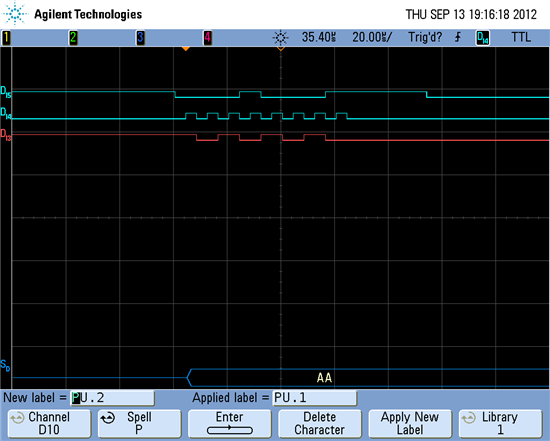
  • Hi,

    i had similar problem, and it turns out this is basically due to the limitation of the USCI module itself. In the users guide you can find the following information:

    as you can see above setting UCCKPH means that data will be first sampled then sent out. And if you see the Figure 33-4 above, you can see that due to this setting, the USCI module will miss the first TX data shift out. Therefore in slave mode, the USCI module shall not be operated with UCCKPH=1.

    Hope this helps.

  • Thanks for the response, Leo. I have looked at that particular figure in the user's guide, but I don't see how the TX data shift and RX sample points are related. It's not as if I am trying to retransmit the byte that is currently being clocked into the USCI. I just want what is already loaded in TXBUF to be clocked out. The RX and TX portions of the USCI operate independently, at least by my interpretation of the user's guide and Figure 35-1 (pasted below).

    My interpretation of Figure 33-4 is that when UCCKPH=1, TX data will always be shifted out on the falling UCxCLK edge so that it is setup for the next rising edge of UCxCLK. Are you saying there is some issue with the USCI module, not mentioned in the latest errata, that prevents this from happening properly when it is operated in slave mode?

  • Hi Ryan,

    from the answer i got from the design team, basically it is not a bug, rather a design limitation. The USCI module works as it is supposed to. Please look again the following simplified of the clock diagram above:

    as you can see, when operated with UCKKPH=1, the first "TX data shifted out" event (red circled) is missing since it has no clocking event.

  • I understand. That's disappointing. I interpreted the diagram to mean that the write to TXBUF is what caused the first TX data shift and the subsequent shifts were done by UCxCLK.  In Figure 35-1, the output of the transmit shift register is connected to the UCxSOMI pin through a tri-state buffer that is controlled by the UCMST bit of UCxCTL0, so I would think that the loading of that shift register (which I presume would happen when TXBUF is written and UCTXIFG is set in UCxSTAT) would make the first bit show up on the output pin.

    Clearly this isn't what actually happens. Are there any workarounds besides changing the clock configuration to not use UCCKPH or changing the master/slave configuration of my design?

  • Hi Ryan,

    personally i am not aware of any workaround for this. I was also just told by design not to use the UCCKPH=1 in slave mode. But let's wait a while to let the other give their minds on this issue.

  • lhend said:
    the first "TX data shifted out" event (red circled) is missing since it has no clocking event.

    I wonder how it can be shifted out if ther eis no clock event. Is it possible that the drawing is wring and the last bit is shifted out at the fineal fallign edge (where it isn't drawn)? THis would reflect the verbal description 'captured at the first edge and sent at the following'

    However, usually, the clock is low-active and the UCKPL bit must be set. In this case, the whoel case snaps into fit. :)

  • Do we expect any further information on this? Whether or not this ends up as an erratum (which it sounds like it won't), I think it needs to be very well documented in the user's guide and datasheet for all the devices where this design limitation exists. It is definitely not obvious from a read of the user's guide and datasheet that slave mode operation with UCCKPH set will not work.

  • Jens-Michael Gross said:
    I wonder how it can be shifted out if there is no clock event

    Well after thinking about it a bit, it looks correct. The first data bit is shifted out immediately if the clock is idle. When the clock goes active, the data is shifted in.
    I tmeans that first data bit is provided at the output before the first clock cycle. Which is perfectly possible when a slave is properly selected through the CS signal. On the 8th clock pulse, the 8th bit is received and when the clock goes idle again, either the first bit of the next data is shifted out or nothing - and CS goes inactive.

    This isn't too different to I2C, where data is output anywhere while the clock is low and shifted in when the clock rises.

    The only problem I see there is that the idle cycle between two byte transmissions might be too short, so that the slave isn't prepared for the next byte when the next clock pulse comes. The idle time between two bytes must be at least as long as the idle time between two clock pulses.

**Attention** This is a public forum