This thread has been locked.

If you have a related question, please click the "Ask a related question" button in the top right corner. The newly created question will be automatically linked to this question.

UART on Launchpad

Other Parts Discussed in Thread: MSP430G2553, MSP430F249

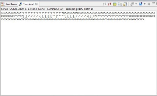
I was using this terminal software TERATERM,in which I'm able to see the output of the UART code running on f2274 board when I used EZ430RF as the debugging interface.But there seems to be no output when I run the similar code on launchpad! Both use virtual COM port but launchpad's USB interface is not working fine with TERATERM.
Also there seems no output on the TERMINAL window of CCS(version 5).I am running the sample codes I got for MSP430g2553 on launchpad.

Which terminal to use(other than Hyperterminal)?More importantly where to view the output of UART code running on Launchpad(MSP430g2553)?

Also when after running the code I input aomething from my keyboard there is no change in the Receive buffer contents of the UART receive buffer register.

Hope you could help.

Thanks.

  • NIKET AGRAWAL said:

    ...there seems no output on the TERMINAL window of CCS(version 5).I am running the sample codes I got for MSP430g2553 on launchpad.

    View > Other > Terminal > Terminal

    .

    .


    This output is correct.  "W" corresponds to 87 °F since W is decimal 87 in the ASCII table.  This sequence shows the temperature rise and then fall.

    NIKET AGRAWAL said:

    Which terminal to use(other than Hyperterminal)?

    Any is fine.  This preference is up to you.  Here are the terminal programs I use:

    Code Composer Studio > View > Other > Terminal > Terminal
    Putty
    HTerm
    TeraTerm

    Here is how it looks on TeraTerm

    This is my setup:

    Hardware: MSP-EXP430G2
    Device: MSP430G2553
    IDE: Code Composer Studio  Version: 5.3.0.00090
    Firmware: C:\MSP430_LaunchPad\Solutions\Lab2\Files\Temperature_Sense_Demo.txt
        Getting Started with the MSP430 LaunchPad Workshop
        Find, "The installation file for the workshop labs"
        Make a new project and run Lab2

    You can also verify the UART communication using the GUI for that project.

  • Hi,

    I tired the exact steps you mentioned but it doesnt work for me. I tried opening the terminal before but it shows nothing. Then I hunted down the problem further and read in one of the forums that the INFO_A segment should not be deleted and sometimes if it is DCO might not work as expected and hence the Baud Rate might be messed up. I don't remember deleting the INFO_A segment. (I even checked the project properties and it says "Erase Main memory only". )

    Then,  I ran the DCO Calibration file found in (C:\..\MSP430G2xx3_Code_Examples\C\msp430g2xx3_dco_flashcal.c). However when I run that code, the LEDs ( 1 and 2) on the launchpad keep blinking indicating that the code doesn't come out of the Set_DCO(16Mhz) function. I am not sure what the exact problem is and I am stuck at this place. Can you please help me?

  • First step is to check if you can echo the bytes sent from PC to device by shortening Tx and Rx on your board.

    Regards,
    Maciej 

  • NIKET AGRAWAL said:
    there seems to be no output when I run the similar code on launchpad!

    Check the jumper settings on the LaunchPad. If you use the G2553, teh two jumpers for RX and TX need to be set horizontally. The default software UART code for the LaunchPad needs them set vertically (RX/TX twisted). Which is AFAIK the default position.

    On older LaunchPad revisions, the G2553 cannot be used this way, as the jumpers do not allow swapping RX and TX.

  • Hello Ti employees,

    I also have the same problem. Here is my initial UART. Does it make sense? I want to have baudrate=115200, 8 bit data, none parity. However, I sendByte('2') to Hercules or Terminal console, the result is not '2'.

    Can you help me?

    ///////

    void initUart()
    {
      // Configure UART pins P3.4 & P3.5
      UART_PORT0 |= UART_PIN4 + UART_PIN5;
          // Configure UART 0
      UCA0CTL1 |= UCSWRST;
      UCA0CTL1 |= UCSSEL_2;                      // Set SMCLK as UCLk
      UCA0BR0 = 8;                              // 115200 baud
      // 16000000/(115200*16) - INT(16000000/(115200*16))=
      UCA0BR1 = 0;
      // UCBRFx = 11, UCBRSx = 0, UCOS16 = 1 (Refer User Guide)
      UCA0MCTL = 0xB1;
      UCA0CTL1 &= ~UCSWRST;                     // release from reset

    //  memset(uartRXBuf,0,sizeof(uartRXBuf));
    }

    int main(void)
    {
    //  int i;
      WDTCTL = WDTPW + WDTHOLD;                 // Stop Watchdog Timer

      DCOCTL = 0;                               // Select lowest DCOx and MODx settings
      BCSCTL1 = CALBC1_16MHZ;                   // Set DCO to 8MHz
      DCOCTL = CALDCO_16MHZ;
    //  P2OUT |= 0X00;
     // P2DIR |= 0x08;

      initUart();

      sendByte('2');
       while(1)
      {
      }  
    }

    //////

  • By the way I think that launchpad will work with only up to 9600. 

    Regards,

    Maciej 

  • MaciejKucia said:
    By the way I think that launchpad will work with only up to 9600. 

    Through the application UART interface, yes. The MSP itself can do more.

    However, without a stable clock source, higher baudrates aren't taht reliable. And the G series only supports the 32768Hz crystal. (great for MIDI interface, but not for 115200Bd serial connections)

  • Jens-Michael Gross said:
    And the G series only supports the 32768Hz crystal. (great for MIDI interface, but not for 115200Bd serial connections)

    32768Hz crystal is good for DCO runtime calibration which then can be used for 115200Bd serial connections.

  • Hello,

    I am using MSP430f249 not G series. When I sent a byte 'c' to buffer TX pin, hercules received another character. Something mistakes in my code.

    Thank you so much!

  • lau lau said:
    I am using MSP430f249 not G series.

    How could we possibly know? This thread is about LaunchPad, which is the G-Series development board. If you don't use the LaunchPad, then your problem is most likely  different from the one discusse din this thread. Even if the symptoms are similar.

    But now that you hijacked this thread, you should provide soem information. We now know that you're using the F249, but we still don't know how you connected this F249 to the rest of the world. What kind of PCB are you using? An experimenters board or an own build? How did you connect the F249 to the PC? What else can you tell? What do you want to do, what did you do (whcih is often enough different), what did you expect and what do you get instead?

    lau lau said:
      BCSCTL1 = CALBC1_16MHZ;                   // Set DCO to 8MHz

    Hmmm,

    lau lau said:
    When I sent a byte 'c' to buffer TX pin
    [...]
    sendByte('2');

    Hmmmm,

    And what is sendByte? You didn't post this (important, not only because suggested by yourself as possibly faulty) part of your code.

    lau lau said:
    hercules received another character.

    Which one? And who is hercules? I only know an ancient hero of this name and a PC graphics card. And the famous detective Hercule Poirot.

  • Here is specific experiment. I matched initialUART with hercules HW below. However, I send '2' from msp430f249 to host computer via bridge UART_To_USB, hercules window received 'š' instead of '2'. why didn't computer received '2'. Something wrong in initial UART or any else?

    //////////////////////

    void initUart()
    {
      // Configure UART pins P3.4 & P3.5
      UART_PORT0 |= UART_PIN4 + UART_PIN5;
          // Configure UART 0
      UCA0CTL1 |= UCSWRST;
      UCA0CTL1 |= UCSSEL_2;                      // Set SMCLK as UCLk

      UCA0BR0 = 8;                              // 115200 baud
      // 16000000/(115200*16) - INT(16000000/(115200*16))=
      UCA0BR1 = 0;
      // UCBRFx = 11, UCBRSx = 0, UCOS16 = 1 (Refer User Guide)
      UCA0MCTL = 0xB1;
    //  UCA0IE |= UCRXIE;                         // Enable RX interrupt

      UCA0CTL1 &= ~UCSWRST;                     // release from reset

    //  memset(uartRXBuf,0,sizeof(uartRXBuf));
    }

    //*****************************************************************************
    //
    //!  \brief Sends a string of characters using the UART module
    //!
    //!  \param  msg is pointer to the null terminated string to be sent
    //!
    //!  \return none
    //
    //*****************************************************************************
    void sendString(char * msg)
    {
      unsigned int i = 0;
    //  char str[20];
    //  memset(str,0,sizeof(str));
    //  itoa(msg[1],str,10);

      for(i = 0; i < strlen(msg); i++)
      {
        while (!(IFG2&UCA0TXIFG));             // USCI_A0 TX buffer ready?
        UCA0TXBUF = msg[i];
      }
    }

    //*****************************************************************************
    //
    //!  \brief Sends a byte
    //!
    //!  \param  b is the byte to be sent through UART
    //!
    //!  \return none
    //
    //*****************************************************************************
    void sendByte(char b)
    {
        while (!(IFG2&UCA0TXIFG));             // USCI_A0 TX buffer ready?
        UCA0TXBUF = b;
    }

    int main(void)
    {
    //  int i;
      WDTCTL = WDTPW + WDTHOLD;                 // Stop Watchdog Timer

      DCOCTL = 0;                               // Select lowest DCOx and MODx settings
      BCSCTL1 = CALBC1_16MHZ;                   // Set DCO to 16MHz
      DCOCTL = CALDCO_16MHZ;
    //  P2OUT |= 0X00;
      P2DIR |= 0x08;

      initUart();

      sendByte('2');
      P2OUT |= 0X08;
      while(1)
      {
      }  
    }
    ////////////////////////

  • anybody can help me deal with this problem?

**Attention** This is a public forum