This thread has been locked.

If you have a related question, please click the "Ask a related question" button in the top right corner. The newly created question will be automatically linked to this question.

MSP430F5510 - Schematic Review

Expert 1485 points

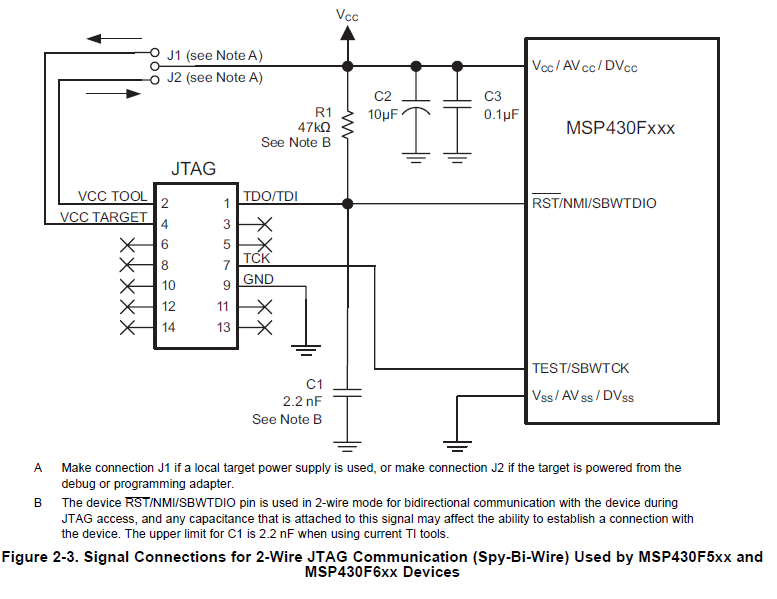
Can you confirm that the circuit below is appropriate for using a reset IC on a spi-bi wire pin on the MSP430.  I seem to have programming problems and I’m not sure what the cause is.  Maybe the resistors are too large.  The bottom picture is from the TLV803S datasheet.  Thank you.


  • Rustin,

    What kind of programming problems are you having with the device? When looking at the MSP430 Hardware Tools doc (http://www.ti.com/lit/ug/slau278l/slau278l.pdf), I've found it's recommended to have a capacitor of max 2.2nF on the RST line for the Spy-Bi-Wire implementation. I've attached a screeenshot from the document below.

    Regards,

    Reagan

  • Hi Rustin,

       I'm not sure what your application requires, but please note that the MSP430F5xx microcontrollers have internal Brown Out Reset (BOR) protection in addition to the Supply Voltage Supervisor (SVS) that may provide the protection you need. 

      The MSP430F5xx Family User's Guide provides details of the SVS in Chapter 2:

    http://www.ti.com/lit/ug/slau208m/slau208m.pdf

      Just a quick paragraph from this document:


       Something to consider for your design.   I think you may need to add the capacitor that Reagan mentioned either way.

        Best,

                 Rick Nardone


  • Rick Nardone said:
    I think you may need to add the capacitor that Reagan mentioned either way.

    Reagan Revisore said:
    I've found it's recommended to have a capacitor of max 2.2nF on the RST line

    The capacitor is to create an RC time constant at poweron. Rustin is using a supervisory chip to provide a hard reset with open-drain and pullup resistor. That is usually a good solution. The issue may be the interaction with the SBW interface. I use the 5510 also, but in full 4-wire JTAG mode. It might be worth looking at the conditions for BSL entry and make sure that's not happening. That, and some more detailed information about what "programming problems" means.

    For starters, I would replace the 47K resistor with a jumper. You want the supervisor to yank the RST line low for a good reset. And make sure that the supervisor has released the reset before programming operations.

  • You might want to take a look at what happens when the emulator tries to access the SBW lines and pulls reset low.  I'm not familiar with this particular reset supervisor, but if it were to trigger its reset when the reset pin is pulled low, it might hold the reset line down when it shouldn't.

    I'd get out the oscope and take a look, maybe post the traces back here in the thread for us to look at?

    Reagan and Rick are right that if you're NOT using an external voltage monitor, the cap is necessary, otherwise the SBW won't work (at least in my experience.)  I'm not sure about how an external supervisor affects things. I've never seen one used on the 5510 before.

    John

  • Rustin,


    Have the proposed fixes resolved the situation?

    Regards,

    Reagan

  • Yes.  Thank you!

**Attention** This is a public forum