This thread has been locked.

If you have a related question, please click the "Ask a related question" button in the top right corner. The newly created question will be automatically linked to this question.

Timer in capture mode in msp430

Other Parts Discussed in Thread: MSP430F6736, MSP430F5438A

Hello,

I am working on msp430f6736.

I am trying to capture signal on P1.1 pin. I m generating 1KHz signal on P2.7 and i m giving same signal on P1.1 for capturing.

But Value in TA0CCR1 remains 0 always.It goes into ISR whenever input is given on P1.1 but TA0CCR1 remains unchanged.

please review it.

thank you.

Following is the code:

#include "msp430.h"
#include "gpio.h"
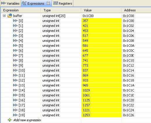
static int buffer[20];
static int i;

void main(void)
{
    WDTCTL = WDTPW + WDTHOLD;
    GPIO_setAsPeripheralModuleFunctionOutputPin (GPIO_PORT_P2,GPIO_PIN7);
    P5DIR |= BIT0;
    P5OUT &= ~BIT0;
    TA1CCTL0 = CCIE;
    TA1CCR0 =32-1;
    TA1CCR1 =16 ;
    TA1CCTL1 = OUTMOD_7;
    TA1CTL = TASSEL_1 + MC_1 + TACLR;

    GPIO_setAsPeripheralModuleFunctionInputPin(GPIO_PORT_P1,GPIO_PIN1);
    TA0CCTL1= CM_1 + CCIS_0 + CAP + SCS + SCCI + CCIE;
    TA0CCTL1 &=~COV;
    TA0CTL = TASSEL_1 + MC_1 + TACLR;
    __bis_SR_register(LPM0_bits | GIE);
}
#pragma vector=TIMER0_A1_VECTOR
__interrupt void TIMER0_A1_ISR(void)
{

  switch(__even_in_range(TA0IV,6))
  {
    case 0: break;                          // No interrupts
    case 4: break;                          // TA0CCR2
    case 2:                                 // TA0CCR1
    {
        buffer[i++] = TA0CCR1;
              if (i>10)
      break;
    }
    case 6: break;                          // TA0CCR3
    default: break;
  }
}

  • allen cooper said:
        TA1CTL = TASSEL_1 + MC_1 + TACLR;

    MC_1 means 'count from 0 to the value in CCR0 and then roll over to 0). Since CCR0 is 0, the timer doesn't count. You'll need to use MC_2 to have the timer counting from 0 to 65535 independently of the content of CCR0.

  • Sorry,but value in TA1CCR0 is 32-1 (31).You are talking about which CCR0.?

    And i am getting PWM on P2.7 correctly.It counts correctly.

    I think problem is in following part.:(for capture)

        GPIO_setAsPeripheralModuleFunctionInputPin(GPIO_PORT_P1,GPIO_PIN1);

        TA0CCTL1= CM_1 + CCIS_0 + CAP + SCS + SCCI + CCIE;
        TA0CCTL1 &=~COV;
        TA0CTL = TASSEL_1 + MC_1 + TACLR;

    Please refer again. Or is there any problem in ISR.?

    Thank you.

  • allen cooper said:
    Sorry,but value in TA1CCR0 is 32-1 (31).You are talking about which CCR0.?

    TA0CCR0.

    The two tiemrs run independently (but from same clock source).
    TA0 is also programmed in up mode, but its TA0CCR0 is 0, so it runs from 0 to 0. (While TimerA1 runs from 0 to TA1CCR0, so form 0 to 31) No matter when you trigger the capture input, you'll get 0 as the current count. A 'different' 0, but 0 anyway.
    Just change the timer mode to MC_2 and you'll start getting values form 0 to 65535. And since the two timers run from same clocksource and you're feeding the output of TimerA1 into TA0CCR1, you'll get results that are 32 counts apart.

  • Thank you for your reply.

    I have changed it to mode 2 (MC_2).

    and i have made some changes in code and ISR.

    But now i am facing another problem.

    Whenever i am free running my code it doesn't execute correctly.

    So,I have tested it by single stepping. And i am getting value in TA0CCR1.

    But difference between two buffer is not constant as i have expected,

    ex. buffer[1]-buffer[0]=421-357=64 and buffer[2]-buffer[1]=453-421=32

    Here below is my code and snapshot of debugger watch window for viewing buffer.

    ------------------------------------------------------------------------------------------------------------------

    unsigned int buffer[20];
    unsigned int i=0;

    void main(void)
    {
        WDTCTL = WDTPW + WDTHOLD;
        GPIO_setAsPeripheralModuleFunctionOutputPin (GPIO_PORT_P2,GPIO_PIN7);          // PWM output pin
        TA1CCTL0 = CCIE;
        TA1CCR0 =32-1;
        TA1CCR1 =16;
        TA1CCTL1 = OUTMOD_7;
        TA1CTL = TASSEL_2 + MC_1 + TACLR;

        GPIO_setAsPeripheralModuleFunctionInputPin(GPIO_PORT_P1,GPIO_PIN1);             // Input pin ,capture
        TA0CCTL1= CM_1 + CCIS_0 + CAP + SCS + CCIE;
        TA0CCTL1 &=~COV;
        TA0CTL = TASSEL_2 + MC_2 + TACLR;
        __bis_SR_register(LPM0_bits | GIE);
        while(1);
    }
    #pragma vector=TIMER0_A1_VECTOR
    __interrupt void TIMER0_A1_ISR(void)
    {

      switch(__even_in_range(TA0IV,6))
      {
        case 0: break;                          // No interrupts
        case 4: break;                          // TA0CCR2
        case 2:                                 // TA0CCR1
        {
            if(i==20)
            {
                TA0CCTL1&=~CCIE;
            }
            else
            {
                buffer[i] = TA0CCR1;
                i++;
            }
            break;
        }
        case 6: break;                          // TA0CCR3
        default: break;
      }
    }

    ----------------------------------------------------------------------------------------

    Please give solution. Is it a synchronization problem?

    Thanks in advance.

  • I'd guess that your TimerA0 ISR is too long to complete within a single cycle of the signal you're generating with TimerA1. The result is that TimerA0 is overwriting previous captures before your ISR gets around to processing them. The COV flag in TA0CCTL1 will get set whenever this happens.

    You only have 32 MCLK cycles between each rising edge of the signal, which is not many to work with. As a test, try setting the input divider on TimerA1 to 8. That will give you 256 MCLK cycles between each rising edge. That should help confirm whether this is the cause of the issue.

  • Hello,

    I am new to MSP430 architecture and working on timers.

    I want to write a small program to capture the PWM signal fed from other pin.

    Details,

    Board : MSP430F5438A experimenter board.

    PWM Output : P8.5/TA1.0 -- Generate PWM with 2KHz correctly

    Input Capture : P1.2/TA0.1


    Code Snippet,

    #include <msp430.h>

    static void Timer_Init(void) {

          /* P8.5 PWM Output*/     P8DIR |= BIT6;     P8SEL |= BIT6 ;     TA1CCR0 = 512-1;                          // PWM Period     TA1CCTL1 = OUTMOD_7;                      // CCR1 reset/set     TA1CCR1 = 256;                            // CCR1 PWM duty cycle     TA1CTL = TASSEL_1 + MC_1 + TACLR;         // SMCLK, up mode, clear TAR         /*P1.2 as input capture */     P1DIR &= ~BIT2;     P1SEL |= BIT2 ;     TA0CTL = TASSEL_1 + MC_2 + TACLR;     TA0CCTL1= CM_1 + CCIS_0 + CAP + SCS + CCIE;     TA0CCTL1 &=~COV;              }


    void main(void) {        Timer_Init();    

         while(1)   {              __bis_SR_register(LPM0_bits + GIE); //Returns if button pressed or clock ticks         __no_operation();                   // For debugger only               }                 }

    #pragma vector=TIMER0_A1_VECTOR __interrupt void TIMER0_A1_ISR(void) {

      switch(__even_in_range(TA0IV,6))   {     case 0: break;                          // No interrupts     case 4: break;                          // TA0CCR2     case 2:  break;                               // TA0CCR1     case 6: break;                          // TA0CCR3     default: break;   } }

    After execution PWM output is generated but when the same PWM is connected to P1.2 these is no interrupt.

    Tried with changes in TA0CCTL1= CM_1 + CCIS_0 + CAP + SCS + CCIE; with CCIS_3, CM_2 etc.

    Thanks in advance.

    Regards,

    Bhushan

  • Hi Allen,

    The code which you have provided is not working as expected on MSP430F5438A.I am not an interrupt, whenever I fed a PWM signal to TA0.1.
    And could you please let me know, What exactly u do in function
    GPIO_setAsPeripheralModuleFunctionInputPin(GPIO_PORT_P1,GPIO_PIN1); // Input pin ,capture

    Thanks
    Bhushan
  • It's a bit difficult to read (you should use the syntax highlighting tool in the rich text editor to post code), but it seems correct and should work.
    You should get interrupts and go into case 2 of your ISR.

    I hope you didn't put a breakpoint on the __no_operation()? The comment there should read "For debugging: don't put a breakpoint here" as you must not put a breakpoint onto the instruction right after entering LPM (hence the NOP) It would be triggered when entering LPM, not after LPM exit (because of the way LPM works and the instruction prefetch of the processor)

    "Tried with changes in TA0CCTL1= CM_1 + CCIS_0 + CAP + SCS + CCIE; with CCIS_3, CM_2 etc."
    Changing CCIS_x from CCIS_0 would listen on P8.1 (CCIS_1), GND or VCC (so never trigger)

    If your ISR doesn't explicitly exit LPM, the comment 'Returns if button pressed' is wrong. It will never return from LPM.
  • Thanks a lot Jens-Michael ,

    I could able to rectify the problem.:)

    As the P1.2 is not connected to any pin in MSP430F5438A experimenter board.
    So here is the port configuration which triggers interrupt and can read duty cycle of pulse.
    To above code adding this configuration makes it work.
    P1DIR &= ~BIT2; // P1.1/TA0.1 Input Capture
    P1SEL |= BIT2; // TA0.1 option select
    P1OUT &= ~BIT2;
    P1REN |= BIT2;

    Thanks
    Bhushan
  • Those changes configure P1.2 to have a pulldown resistor enabled. However, if you connected the output of the PWM to P1.2, it should work without. If not, all you might detect is the initial pin change when the pulldown gets enabled, but no duty cycles
  • Thanks Jens-Michael Gross.

    You are right..!

    I try to test the same by disabling the pull down resistor. And As you mentioned it triggers an interrupt due to initial pin changes.
    Seems some problem with connection between the PWM output and P1.2 when I tried yesterday.

    Anyways it was really helpful.

    Regards,
    Bhushan

**Attention** This is a public forum