This thread has been locked.

If you have a related question, please click the "Ask a related question" button in the top right corner. The newly created question will be automatically linked to this question.

What is the distinction between OUTMOD0 and OUTMOD_0?

Other Parts Discussed in Thread: MSP430G2553

In the MSP430G2553.h there are these definitions for the timer:

#define OUTMOD2                (0x0080)       /* Output mode 2 */
#define OUTMOD1                (0x0040)       /* Output mode 1 */
#define OUTMOD0                (0x0020)       /* Output mode 0 */

and

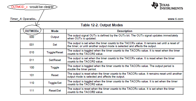
#define OUTMOD_0               (0*0x20u)      /* PWM output mode: 0 - output only */
#define OUTMOD_1               (1*0x20u)      /* PWM output mode: 1 - set */
#define OUTMOD_2               (2*0x20u)      /* PWM output mode: 2 - PWM toggle/reset */
#define OUTMOD_3               (3*0x20u)      /* PWM output mode: 3 - PWM set/reset */

  • OUTMOD0 specifies the zeroeth bit of the OUTMOD field of the TACCTLx registers. It's a bitmask that you would use if you want to set/clear that specific bit of the output mode.

    OUTMOD_0 is a value that, when assigned to TACCTLx, will set the appropriate bits of the OUTMOD field to select "output only" mode. These values are present in the header for convenience, as they remove the need to set bits of the OUTMOD field individually.

    The last four defines in your post could be rewritten as:

    #define OUTMOD_0 (0)                 /* PWM output mode: 0 - output only */
    #define OUTMOD_1 (OUTMOD0)           /* PWM output mode: 1 - set */
    #define OUTMOD_2 (OUTMOD1)           /* PWM output mode: 2 - PWM toggle/reset */
    #define OUTMOD_3 (OUTMOD1 | OUTMOD0) /* PWM output mode: 3 - PWM set/reset */

    In other words, you could select output mode 3 by either of these methods:

    TACCTL1 = OUTMOD_3;
    TACCTL1 = OUTMOD1 | OUTMOD0;
  • Robert, thanks.

    It is more convenient. I was just using OUTMOD_5 and instead of locating the actual bit positions in the register, I can just:

    TACCTL1 |= OUTMOD2 + OUTMOD0;

    TACCTL1 &= ~OUTMOD1;

  • Joseph Raslavsky said:
    I was just using OUTMOD_5 and instead of locating the actual bit positions in the register, I can just:

    TACCTL1 |= OUTMOD2 + OUTMOD0;
    TACCTL1 &= ~OUTMOD1;

    You can as well do
    TACCTL1 &=OUTMOD_7; //clear all OUTMOD bits
    TACCTL1 |= OUTMOD_5;
    It is easier to read later, as you don't have to claculate what OUTMOD2 and OUTMOD0 btu not OUTMOD1 will give for an OUTMODe :)

    BZW: it is more efficient to combine the two lines into one. Especially since you don't have an intermediate OUTMOD setting then:

    TACCTL1 = (TACCTL1 & ~OUTMOD_7) | OUTMOD_5;

  • Jens-Michael Gross said:

    BZW: it is more efficient to combine the two lines into one. Especially since you don't have an intermediate OUTMOD setting then:

    TACCTL1 = (TACCTL1 & ~OUTMOD_7) | OUTMOD_5;

    Jens-Michael: Thanks for that. I like that. And if it means the compiler will do it in one instruction versus two without requiring optimization, so much the better.

    And if anyone from Ti is listening let me say that while I find most of your documentation pretty darn good, I find one thing in your tables that was confusing for me as a recent user of your micro. And that is your neglect to use the underscore in describing the particular mode in your tables, when in fact the underscore is essential. For example, (or BZW as Jens would say), you use OUTMODx when you could prevent the engineer from hunting for the actual mnemonic by using OUTMOD_x. Or worse, as in this case,  OUTMODx actually has a value when x = 0 and caused a problem for me when I used OUTMOD0 rather than OUTMOD_x.  Edit: OUTMOD_0.

    Here's an example from User Guide slau144i p372:

  • That's a good point, Joseph. I suggest you submit that feedback directly to TI using the link in the page footer of the user guide.

  • Robert Cowsill said:

    That's a good point, Joseph. I suggest you submit that feedback directly to TI using the link in the page footer of the user guide.

    Robert,  

       Done. Pretty nice feature in the manual to provide a link in the footer for feedback.


  • Robert Cowsill said:
    That's a good point, Joseph.


    Sorry, I have to disagree. The users guide defines the bits only. The defines with underlines (or even double-underlines) are convenience defines. Enumerations. They are not defined in the register descriptions anywhere, and therefore do not belong into lists too. However, a different notation could be used, especially in this table, since there is no OUTMOD111 or OUTMOD101 (which people could assume by replacing the x with the value in the table).

    Of course it wouldn't hurt to explain the nomenclature way better. However, you won't see any 'underline define' anywhere in the users guide tables or register descriptions. But since they are used in some of the examples, they shoul dbe explained in detail (well, I bet people wouldn't read the chapter with the explanation then - people only read what they think they'll need - without the knowledge to know what they need)

    Joseph Raslavsky said:
    Pretty nice feature in the manual to provide a link in the footer for feedback.

    Those links were gone from newer documents yars ago. I'm surprised to see them back again.

  • Jens-Michael Gross said:

    Sorry, I have to disagree. The users guide defines the bits only. The defines with underlines (or even double-underlines) are convenience defines. Enumerations. They are not defined in the register descriptions anywhere, and therefore do not belong into lists too. However, a different notation could be used, especially in this table, since there is no OUTMOD111 or OUTMOD101 (which people could assume by replacing the x with the value in the table).

    Actually, you're right there Jens-Michael. I was concerned about the "collision" between the nomenclature in the user guide and the "wrong" set of constants in the header. Changing the user guide to match the other set of constants probably isn't the best way to fix that issue after all.

  • Robert Cowsill said:
    Changing the user guide to match the other set of constants probably isn't the best way to fix that issue after all.

    There's actually a third set of defines: the double-underscores.

    These get their names based on the meaning of an option.
    e.g. the timer input divider field IDx
    There's ID0 and ID1 for the bits. There's ID_0..ID_3 for the four possible combinations, and there's ID__1, ID__2, ID__4 and ID__8 representing the resulting input divider effect. To make it more confusing, the second underscore is only used when the suffix is a number. In case of OUTMODx, there's OUTMOD_OUT, OUTMOD_SET. OUTMOD_TOGGLE_RESET etc.
    And for the beforementioned ID__2, there's ID_DIV2 too.
    However, these are (at least partly) compiler-dependent. They are just convenience-defines and no official symbols.

  • Jens-Michael Gross said:

    That's a good point, Joseph.


    Sorry, I have to disagree. The users guide defines the bits only. The defines with underlines (or even double-underlines) are convenience defines. Enumerations. They are not defined in the register descriptions anywhere, and therefore do not belong into lists too. However, a different notation could be used, especially in this table, since there is no OUTMOD111 or OUTMOD101 (which people could assume by replacing the x with the value in the table).

    Of course it wouldn't hurt to explain the nomenclature way better. However, you won't see any 'underline define' anywhere in the users guide tables or register descriptions. But since they are used in some of the examples, they shoul dbe explained in detail (well, I bet people wouldn't read the chapter with the explanation then - people only read what they think they'll need - without the knowledge to know what they need)

    [/quote]

    "Of course it wouldn't hurt to explain the nomenclature way better. However, you won't see any 'underline define' anywhere in the users guide tables or register descriptions."

    That's my point. Why leave out a simple underline when including it just makes sense. And it's of no benefit to have two names for the same object, especially when there can be conflict with the same name.

    At this stage in my learning curve of the MSP430 I now know to search the appropriate header file or look through example code to quickly find the actual mnemonic. But it would've been better for me, and I suspect future new users, had the User Guide look something like this:

  • Joseph Raslavsky said:
    But it would've been better for me, and I suspect future new users, had the User Guide look something like this:

    Well, MSP developemnt in C expects you to know C and to know to look into the headers :)

    I understand your problem. However,. you look at it top-down while the description is writte bottom-up. SREFx are control bits. SREF is a bitfield and teh original definition describes its bits and bit combinations. You see, most of the users guide examples are in assembly. The undescore-defines are a back-port from C to assembly, if available at all.

    Also, using SREF_x in teh decription would somewhat obfuscate the fact that this is a bit combination. You wouldn't believe how many people forget to mask the existing bits before switching to a different selection, using the underscore-defines.

    Either way, without a 'tutorial', either implementation wil raise problems.

  • Jens-Michael Gross said:

    But it would've been better for me, and I suspect future new users, had the User Guide look something like this:

    Well, MSP developemnt in C expects you to know C and to know to look into the headers :)

    Also, using SREF_x in teh decription would somewhat obfuscate the fact that this is a bit combination. You wouldn't believe how many people forget to mask the existing bits before switching to a different selection, using the underscore-defines.

    Either way, without a 'tutorial', either implementation wil raise problems.

    [/quote]

    Yes. SREF_3 actually represents two bits and as such is obfuscating. I leave it to more experience heads to implement a solution. But my post remains as a suggestion.

    It seems to me the ideal place to put the code mnemonics is in the user guide where you have to go anyway to see how to set up the register bits. It saves the user the task of hunting for them or doing as I do, using the definitions as a memory aid or as a clue in guessing. Memory and guessing would be replaced by certitude. Maybe just do it for electronic documents where a mouse click would bring up the mnemonic, saving the engineer the mundane task of locating it.

  • Joseph Raslavsky said:
    Yes. SREF_3 actually represents two bits and as such is obfuscating. I leave it to more experience heads to implement a solution.

    Well, on earlier generations of the compilers, the header files contained bitfield declarations for the hardware registers.
    So you could do ADC10CTL0.SREF = SREF_3; (SREF_x being 0..7)
    The compiler was doing the masking for you then. However, it had to do it all the time, evne if not required. And assigning more than one setting required individual operations. And since the hardware registers are volatile, the compiler cannot do any optimization on such a construct. So it turned out to be very ineffective, even though very convenient.
    The bitfields are gone now, but the undeline-defines are still there, as sort of a 'replacement'.

**Attention** This is a public forum