This thread has been locked.

If you have a related question, please click the "Ask a related question" button in the top right corner. The newly created question will be automatically linked to this question.

I2C interfacing of CC430F5137 with SHT21

Other Parts Discussed in Thread: CC430F6137, CC430F5137

Hi,

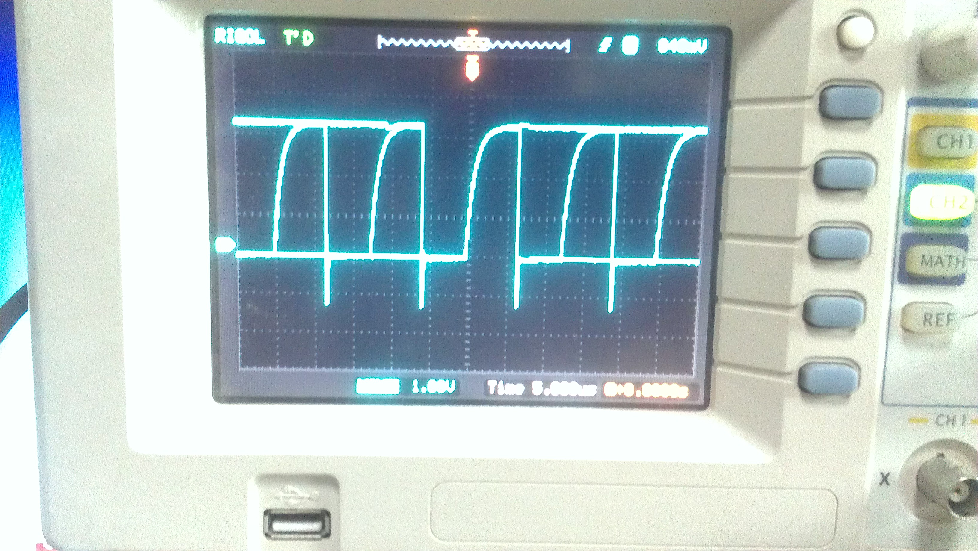
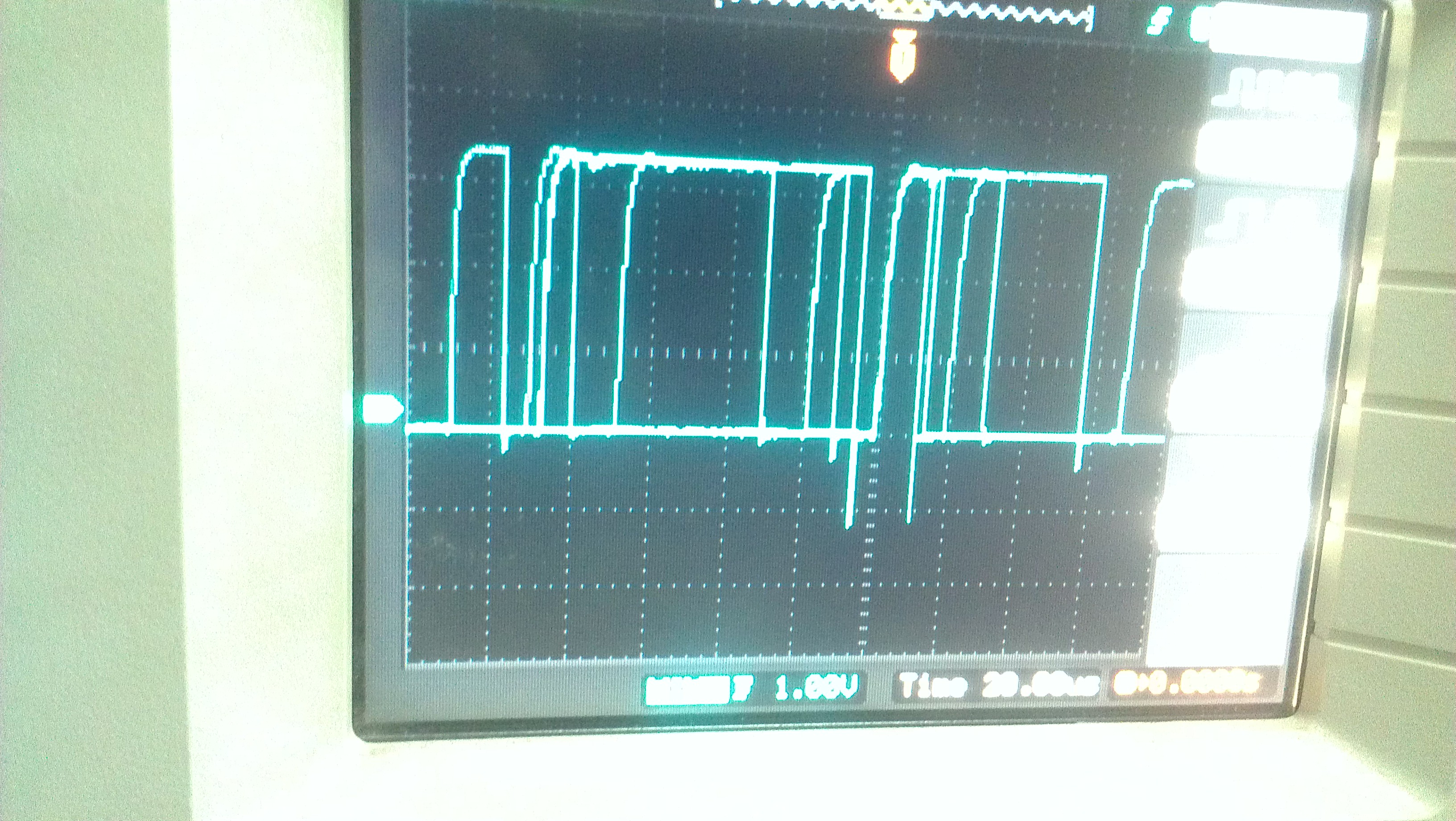
I am interfacing SHT21 temp/humidity sensor with CC430F6137 micro-controller. I have seen one of the post related to this matter but I have facing different problem. My controller send stop condition, start condition and address of the Slave but never gets Ack from the SHT21. I have also attached a screen shot of logic analyzer with this post.

Could anybody help me how I can fix this problem. How can I check that my sensor is working fine. I have change two sensor but every time I get the same result as shown above. Any kind of help would be appreciated.

  • The slave address looks correct, also the signals. So if the slave doesn't answer, this may have several reasons. The two most common ones are:

    Do you have a common GND for MSP and sensor?
    Did you check the sensors required input voltage level? If the sensor doesn't 'hear' the MSP, it won't ACK. It requires at least 0.7*Vdd, so if the sensor runs on 3.6V, the MSP has to run on at least 2.6V. Also, the low voltage must be below 0.4V. How strong are your pullups? Can they cause 0.4V voltage drop on the MSP port pin?

  • Thanks Jens for replying.

    Do you have a common GND for MSP and sensor?

    Yes I have common GND for MSP and sensor.

    Actually I am using 3 V for MSP as well for sensor. Providing 3 V to sensor from the same source.

    How strong are your pullups?

    I am using 10K pull up resisters.

    Can they cause 0.4V voltage drop on the MSP port pin?

    No. I can see almost the same voltage as coming from the source at MSP port pin.

    Do I have to choose pull up resister more than 10K.

  • Here is some more information.

    MSP and sensor voltage => 3.065V (GND is common)

    When I2C program is running then multi-meter shows the following readings and logic analyzer reading is same as shown above

    SDA port pin voltage =>1.346V

    SCL port pin voltage => 1.258V

    also the voltage drop accross the pullup resisters are

    SDA=> 1.717V

    SCL=>1.812V

    When I2C program is not running then multi-meter shows the following readings and logic analyzer shows nothing

    SDA port pin voltage =>3.021V

    SCL port pin voltage => 3.025V

    Waiting for your reply.
  • Please waiting for reply...

  • Here is my code which I am using for testing...the code is only sending the address and data

    //******************************************************************************
    //  CC430F613x Demo - USCI_B0 I2C Master TX single bytes to MSP430 Slave
    //
    //  Description: This demo connects two MSP430's via the I2C bus. The master
    //  transmits to the slave. This is the master code. It continuously
    //  transmits 00h, 01h, ..., 0ffh and demonstrates how to implement an I2C
    //  master transmitter sending a single byte using the USCI_B0 TX interrupt.
    //  ACLK = n/a, MCLK = SMCLK = BRCLK = default DCO = ~1.045MHz
    //
    //                                /|\  /|\
    //               CC430F6137      10k  10k     CC430F6137
    //                   slave         |    |        master
    //             -----------------   |    |   -----------------
    //           -|XIN  P2.6/UCB0SDA|<-|----+->|P2.6/UCB0SDA  XIN|-
    //            |                 |  |       |                 | 32kHz
    //           -|XOUT             |  |       |             XOUT|-
    //            |     P2.7/UCB0SCL|<-+------>|P2.7/UCB0SCL     |
    //            |                 |          |             P1.0|--> LED
    //
    //   M Morales
    //   Texas Instruments Inc.
    //   April 2009
    //   Built with CCE Version: 3.2.2 and IAR Embedded Workbench Version: 4.11B
    //******************************************************************************

    #include "cc430x613x.h"
    int a=0;
    unsigned char TXData;
    unsigned char TXByteCtr;

    void main(void)
    {
      WDTCTL = WDTPW + WDTHOLD;                 // Stop WDT

      __delay_cycles(2000000);
      P1OUT &= ~BIT0;
         P1DIR |= BIT0;
         P3OUT &= ~BIT6;
             P3DIR |= BIT6;
      PMAPPWD = 0x02D52;                        // Get write-access to port mapping regs
      P2MAP6 = PM_UCB0SDA;                      // Map UCB0SDA output to P2.6
      P2MAP7 = PM_UCB0SCL;                      // Map UCB0SCL output to P2.7
      PMAPPWD = 0;                              // Lock port mapping registers
     
      P2SEL |= BIT6 + BIT7;                     // Select P2.6 & P2.7 to I2C function

     
      UCB0CTL1 |= UCSWRST;                      // Enable SW reset
      UCB0CTL0 = UCMST + UCMODE_3 + UCSYNC;     // I2C Master, synchronous mode
      UCB0CTL1 = UCSSEL_2 + UCSWRST;            // Use SMCLK, keep SW reset
      UCB0BR0 = 12;                             // fSCL = SMCLK/12 = ~100kHz
      UCB0BR1 = 0;

      //0x80 is the address of sht21
      //UCB0I2CSA = 0x48;                         // Slave Address is 048h
      UCB0I2CSA = 0x40;                         // Slave Address is 040h
      UCB0CTL1 &= ~UCSWRST;                     // Clear SW reset, resume operation
      UCB0IE |= UCTXIE;                         // Enable TX interrupt
      UCB0IE |= UCNACKIE;
      TXData = 0xF3;                            // Holds TX data

      while (1)
      {
        TXByteCtr = 0x01;                          // Load TX byte counter

        while (UCB0CTL1 & UCTXSTP);             // Ensure stop condition got sent
        UCB0CTL1 |= UCTR + UCTXSTT;             // I2C TX, start condition
       
        //__delay_cycles();
        __bis_SR_register(LPM0_bits + GIE);     // Enter LPM0 w/ interrupts

        __no_operation();                       // Remain in LPM0 until all data
                                                // is TX'd
        if(a==1)
        {

            UCB0CTL1 |= UCTXSTP;                  // I2C stop condition
            //__delay_cycles(50);
            a=0;
        }

        //TXData++;                               // Increment data byte
      }
    }

    //------------------------------------------------------------------------------
    // The USCIAB0_ISR is structured such that it can be used to transmit any
    // number of bytes by pre-loading TXByteCtr with the byte count.
    //------------------------------------------------------------------------------
    #pragma vector = USCI_B0_VECTOR
    __interrupt void USCI_B0_ISR(void)
    {
      switch(__even_in_range(UCB0IV,12))
      {
      case  0: break;                           // Vector  0: No interrupts
      case  2: break;                           // Vector  2: ALIFG
      case  4:
         // UCB0CTL1 |= UCTXSTP;                  // I2C stop condition
                a=1;
          __bic_SR_register_on_exit(LPM0_bits); // Exit LPM0

          break;                           // Vector  4: NACKIFG
      case  6: break;                           // Vector  6: STTIFG
      case  8: break;                           // Vector  8: STPIFG
      case 10: break;                           // Vector 10: RXIFG
      case 12:                                  // Vector 12: TXIFG  
        if (TXByteCtr)                          // Check TX byte counter
        {
          UCB0TXBUF = TXData;                   // Load TX buffer
          TXByteCtr--;                          // Decrement TX byte counter
        }
        else
        {
            //P3OUT ^= BIT6;                    // Toggle LED1

          UCB0CTL1 |= UCTXSTP;                  // I2C stop condition
          UCB0IFG &= ~UCTXIFG;                  // Clear USCI_B0 TX int flag

          __bic_SR_register_on_exit(LPM0_bits); // Exit LPM0
        }
        break;
      default: break;
      }
    }

  • Since you don't get an ACK from the slave, the problem is apparently not the code. The logic analyzer confirms that you're sending a write request to a slave with address 0x40. And the slave doesn't answer.
    So far, the code does what it is intended to do and the slave doesn't.
    That's why I quesitoned the voltage levels.

    The values you measured are as expected - and tell nothing. You're apparently using a multimeter, which is giving an average voltage over a large amount of time. What is needed are the actual voltage levels at any particular moment. The only way to get them is using a scope. Unless you lower the baudrate to 0.1Hz, so the multimeter is fast enough :)

  • Thanks Jens-Michael for replying. I have taken some snapshots of oscilloscope to capture the SCL and SDA data. Upper and lower voltage level seems OK. I did not understand why there is ripple in the signal this may cause the the slave to not respond.

    Snapshot of SCL is

    Snapshot of SDA is given below

    I have checked all the connection which is looking OK. But I do not understand why there is noise in data. Is there anything which I am missing?

  • These 'undershoots' look strange. No idea where they come from.
    Also, the rising times of the signal are quite long. I'd suggest a stronger pullup resistor.

    The SDA line looks suspicious too. If the SCL clock pulses are so clean, the data lines should change their level in a similar timing and not so scattered. You should put both on one screen (with offset, so one on upper and one on lower half of the screen).

    You can set the trigger on the first falling edge of SDA (the start condition) and pick the timing so you will see the beginning of just one transfer (start byte and maybe first data byte). It makes the situation more clear.

  • Thanks Jens for reply.

    "the rising times of the signal are quite long. I'd suggest a stronger pullup resistor"

    Yes it's true. rising time is quite long. I changed the pull up resistors 10K with 1K and now rising time is quite short.

    At-least I can get Ack from sensor first time but not after that. For example, after initialization of the I2C module, start condition is sent followed by the slave address. An Ack is received from the slave and command byte is sent by the master. when I again send the start condition with write bit to slave then it never respond and NACK is received by the master.

    I tried to start another transaction by initializing the I2C module. but could not get any ACK. I am trying to get a complete control on the sensor before reading the data from the sensor but could not succeed yet. Please find the code below


    #include "cc430x613x.h"
    int a=0,b=0;
    unsigned char TXData;
    unsigned char TXByteCtr;

    void main(void)
    {
      WDTCTL = WDTPW + WDTHOLD;                 // Stop WDT

      //__delay_cycles(2000000);
      P1OUT &= ~BIT0;
         P1DIR |= BIT0;
         P3OUT &= ~BIT6;
             P3DIR |= BIT6;
      PMAPPWD = 0x02D52;                        // Get write-access to port mapping regs
      P2MAP6 = PM_UCB0SDA;                      // Map UCB0SDA output to P2.6
      P2MAP7 = PM_UCB0SCL;                      // Map UCB0SCL output to P2.7
      PMAPPWD = 0;                              // Lock port mapping registers

      P2SEL |= BIT6 + BIT7;                     // Select P2.6 & P2.7 to I2C function

      /*PMAPPWD = 0x02D52;                        // Get write-access to port mapping regs
                P1MAP0 = PM_UCB0SDA;                      // Map UCB0SDA output to P2.6
                P1MAP1 = PM_UCB0SCL;                      // Map UCB0SCL output to P2.7
                PMAPPWD = 0;                              // Lock port mapping registers

                P1SEL |= BIT2 + BIT1;
    */
      UCB0CTL1 |= UCSWRST;                      // Enable SW reset
      UCB0CTL0 = UCMST + UCMODE_3 + UCSYNC;     // I2C Master, synchronous mode
      UCB0CTL1 = UCSSEL_2 + UCSWRST;            // Use SMCLK, keep SW reset
      UCB0BR0 = 12;                             // fSCL = SMCLK/12 = ~100kHz
      UCB0BR1 = 0;

      //0x80 is the address of sht21
      //UCB0I2CSA = 0x48;                         // Slave Address is 048h
      UCB0I2CSA = 0x40;                         // Slave Address is 040h
      UCB0CTL1 &= ~UCSWRST;                     // Clear SW reset, resume operation
      UCB0IE |= UCTXIE;                         // Enable TX interrupt
      UCB0IE |= UCNACKIE;
      TXData = 0xF3;                            // Holds TX data

      while (1)
      {
        TXByteCtr = 0x01;                          // Load TX byte counter
        while (UCB0CTL1 & UCTXSTP);             // Ensure stop condition got sent
        UCB0CTL1 |= UCTR + UCTXSTT;             // I2C TX, start condition

        __bis_SR_register(LPM0_bits + GIE);     // Enter LPM0 w/ interrupts

        __no_operation();                       // Remain in LPM0 until all data
                                                               // is TX'd
        if(a==1)
        {
            UCB0CTL1 |= UCTXSTP;                  // I2C stop condition
            a=0;
             while (UCB0CTL1 & UCTXSTP);             // Ensure stop condition got sent
         UCB0CTL1 |= UCSWRST;                      // Enable SW reset
          UCB0CTL0 = UCMST + UCMODE_3 + UCSYNC;     // I2C Master, synchronous mode
          UCB0CTL1 = UCSSEL_2 + UCSWRST;            // Use SMCLK, keep SW reset
          UCB0BR0 = 12;                             // fSCL = SMCLK/12 = ~100kHz
          UCB0BR1 = 0;

          UCB0I2CSA = 0x40;                         // Slave Address is 040h
          UCB0CTL1 &= ~UCSWRST;                     // Clear SW reset, resume operation
          UCB0IE |= UCTXIE;                         // Enable TX interrupt
          UCB0IE |= UCNACKIE;
          TXData = 0xF3;                            // Holds TX data


        }
       

        }
    }

    //------------------------------------------------------------------------------
    // The USCIAB0_ISR is structured such that it can be used to transmit any
    // number of bytes by pre-loading TXByteCtr with the byte count.
    //------------------------------------------------------------------------------
    #pragma vector = USCI_B0_VECTOR
    __interrupt void USCI_B0_ISR(void)
    {
      switch(__even_in_range(UCB0IV,12))
      {
      case  0: break;                           // Vector  0: No interrupts
      case  2: break;                           // Vector  2: ALIFG
      case  4:
                a=1;
          __bic_SR_register_on_exit(LPM0_bits); // Exit LPM0

          break;                           // Vector  4: NACKIFG
      case  6: break;                           // Vector  6: STTIFG
      case  8: break;                           // Vector  8: STPIFG
      case 10: break;                           // Vector 10: RXIFG
      case 12:                                  // Vector 12: TXIFG
        if (TXByteCtr)                          // Check TX byte counter
        {
          UCB0TXBUF = TXData;                   // Load TX buffer
          TXByteCtr--;                          // Decrement TX byte counter
        }
        else
        {

          UCB0IFG &= ~UCTXIFG;                  // Clear USCI_B0 TX int flag
          b=1;
          __bic_SR_register_on_exit(LPM0_bits); // Exit LPM0
        }
        break;
      default: break;
      }
    }


  • First thing, all global variables that are used in both, main and an ISR, need to be declared volatile. Else main won't notice that they have been magically changed by an ISR, or main won't actually perform the write before going into LPM, so the ISR won't see their intended content.

    Maybe that's all already.

    However, your 0xf3 command may make the slave temporarily unavailable, so it responds with NACK to the next attempt. Then you switch to a different slave address and never get back for a second try.

    Also, there is no need to completely reprogram the USCI once a connection failed. The new slave address can be set without setting SWRST first. (this is only required for changing the own address). However, this is just superfluous code, not dangerous.

  • thanks Jens for replying.

    "However, your 0xf3 command may make the slave temporarily unavailable, so it responds with NACK to the next attempt. Then you switch to a different slave address and never get back for a second try."

    I am trying with the same slave as I used above. I think there is a mistake due to commenting slave address which is confusing it with other. From the beginning slave address is same 0x40.

  • Awais Aslam said:
    I am trying with the same slave as I used above.

    Ah, okay, yes, I didn't notice the line with 0x48 was commented out.
    So all the code inside the if clause is superfluous. No need to reset the USCI after a NACK.

    Still the missing volatile tag can be a problem. For the compiler, you only set A to 0 but test it for being 1. You don't call a function inside main and therefore the compiler assumes that A is never changed. And optimizes the code in an unexpected way. (note: interrupts are NOT part of the C language specification and therefore something the compiler does not and cannot consider when optimizing the code)

  • It means global variable "TXByteCtr" is also optimized by the compiler because it is not changing its value inside the main but used by the ISR. ISR will not get any updated value of TXByteCtr and may perform unexpected functionality.

  • Awais Aslam said:
    It means global variable "TXByteCtr" is also optimized by the compiler because it is not changing its value inside the main

    Right. The change to 1 might have been moved outside the while loop, right to the beginning. Or it is not set to 1 because it is never read afterwards - the compiler may delay changes to global vars until the next function call, during which it could be accessed - and you don't call a function. Or to the end of the current code block (but you never exit the while loop). Volatile variables are always handled as soon and as often as written in the code. But OTOH it makes the code bigger and slower due to the limitation in optimizing the code then.

  • I tried your suggestion and changed the variable to volatile variables but I could not succeed to get the output from the sensor. I just make changes in the code and use polling instead of ISR and my code start working and I also get the desire output from the sensor. I think I am making any mistake in interrupt based code. Anyhow I am really thankful for being helpful.

  • Dear Awais and jens,

                         I m trying to read the temperature value from sht25 from cc430f5137 and wants to print the value on console but i am unable to get the acknowledgement from receive buffer.Can anyboday point out the problem in my code .or if you have done with the saqme sort of polling then can you share your code here.Urgent response would be highly appreciated in this regard

    #include <msp430.h>
    #include <stdio.h>
    #include<string.h>
    #include"types.h"

    #include <stdint.h> // Integers of defined sizes

    #define SLAVE_ADDRESS_WRITE 0x40   // I2C address 
    #define LED7 BIT7
    #define LED6 BIT6

    void main (void)
    {
    WDTCTL = WDTPW | WDTHOLD;

    unsigned int i,a;
    P3DIR |= LED6 +LED7;
    P3OUT &= ~(LED6 +LED7);

    uint16_t Temp;
    // Stop watchdog timer
    PMAPPWD = 0x02D52;
    P1MAP2 = PM_UCB0SCL; // Map UCA0RXD output to P2.6
    P1MAP3 = PM_UCB0SDA;
    PMAPPWD = 0;

    P1SEL |= BIT2 + BIT3;
    //P1SEL |= BIT2 + BIT3;
    // Assign I2C pins to USCI_B0
    // 7-bit addresses (default), single master , master mode , I2C , synch


    UCB0CTL0 = UCMST | UCMODE_3 | UCSYNC;
    // Clock from SMCLK , receiver (default), hold in reset
    UCB0CTL1 = UCTR|UCSSEL_2|UCSWRST;
    UCB0BR1 = 0; // Upper byte of divider word
    UCB0BR0 = 12; // Clock = SMCLK / 10 = 100 KHz
    UCB0CTL1 &= ~UCSWRST; // Release from reset

    for (;;)
    {
    volatile unsigned int j;
    UCB0I2CSA = SLAVE_ADDRESS_WRITE;
    UCB0TXBUF = 0xE3; //hold master mode


    while((UCB0CTL1 & UCTXSTT) && !(UCB0IFG & UCNACKIFG));


    UCB0I2CSA = 0x40; // Slave Address

    UCB0CTL1 &=~UCTR;  // I2C RX
    UCB0CTL1 |= UCTXSTT;      // Start again for reception

    while((UCB0CTL1 & UCTXSTT) && !(UCB0IFG & UCNACKIFG));   // Wait unitl start and address sent

    for (i=0; i<2; i++)
    {
    P3OUT=LED7;
    while ((UCB0IFG & UCRXIFG)==0); // code hangs here 

    P3OUT=LED6;
    if(i==0)

    Temp= UCB0RXBUF<<8;

    UCB0CTL1 |= UCTXSTP;
    if(i==1)
    Temp |= UCB0RXBUF;

    }
    while(UCB0CTL1 & UCTXSTP);
    printf("Hello world %d", Temp);

    }

    }

    Regards

    Faisal Ali Khan

  • Dear Awais and jens,

                         I m trying to read the temperature value from sht25 from cc430f5137and wants to print the value on console but i am unable to get the acknowledgement from receive buffer.Can anyboday point out the problem in my code .or if you have done with the saqme sort of polling then can you share your code here.Urgent response would be highly appreciated in this regard

    #include <msp430.h> 
    #include <stdio.h>
    #include<string.h>
    #include"types.h"

    #include <stdint.h> // Integers of defined sizes

    #define SLAVE_ADDRESS_WRITE 0x40   // I2C address 
    #define LED7 BIT7
    #define LED6 BIT6

    void main (void)
    {
    WDTCTL = WDTPW | WDTHOLD;

    unsigned int i,a;
    P3DIR |= LED6 +LED7;
    P3OUT &= ~(LED6 +LED7);

    uint16_t Temp;
    // Stop watchdog timer
    PMAPPWD = 0x02D52;
    P1MAP2 = PM_UCB0SCL; // Map UCA0RXD output to P2.6
    P1MAP3 = PM_UCB0SDA;
    PMAPPWD = 0;

    P1SEL |= BIT2 + BIT3;
    //P1SEL |= BIT2 + BIT3;
    // Assign I2C pins to USCI_B0
    // 7-bit addresses (default), single master , master mode , I2C , synch


    UCB0CTL0 = UCMST | UCMODE_3 | UCSYNC;
    // Clock from SMCLK , receiver (default), hold in reset
    UCB0CTL1 = UCTR|UCSSEL_2|UCSWRST;
    UCB0BR1 = 0; // Upper byte of divider word
    UCB0BR0 = 12; // Clock = SMCLK / 10 = 100 KHz
    UCB0CTL1 &= ~UCSWRST; // Release from reset

    for (;;)
    {
    volatile unsigned int j;
    UCB0I2CSA = SLAVE_ADDRESS_WRITE;
    UCB0TXBUF = 0xE3; //hold master mode


    while((UCB0CTL1 & UCTXSTT) && !(UCB0IFG & UCNACKIFG));


    UCB0I2CSA = 0x40; // Slave Address

    UCB0CTL1 &=~UCTR;  // I2C RX
    UCB0CTL1 |= UCTXSTT;      // Start again for reception

    while((UCB0CTL1 & UCTXSTT) && !(UCB0IFG & UCNACKIFG));   // Wait unitl start and address sent

    for (i=0; i<2; i++)
    {
    P3OUT=LED7;
    while ((UCB0IFG & UCRXIFG)==0); // code hangs here 

    P3OUT=LED6;
    if(i==0)

    Temp= UCB0RXBUF<<8;

    UCB0CTL1 |= UCTXSTP;
    if(i==1)
    Temp |= UCB0RXBUF;

    }
    while(UCB0CTL1 & UCTXSTP);
    printf("Hello world %d", Temp);

    }

    }

    Regards

    Faisal Ali Khan

  • Try this ..........

    void main(void)
    {
    int k;
    volatile float temp,humi;
    unsigned char TXData_HT;
    unsigned char TXData_Temp;
    unsigned char usr_reg;
    WDTCTL = WDTPW + WDTHOLD; // Stop WDT


    //************port lock for f5137 ********//
    PMAPPWD = 0x02D52; // Get write-access to port mapping regs
    P3MAP0 = PM_UCB0SDA; // Map UCB0SDA output to P1.0
    P3MAP1 = PM_UCB0SCL; // Map UCB0SCL output to P1.1
    PMAPPWD = 0; // Lock port mapping registers
    P3SEL |= BIT0 + BIT1;
    //***************************************//
    UCB0CTL1 |= UCSWRST; // Enable SW reset
    UCB0CTL0 = UCMST + UCMODE_3 + UCSYNC; // I2C Master, synchronous mode
    UCB0CTL1 = UCSSEL_2 + UCSWRST; // Use SMCLK, keep SW reset
    UCB0BR0 = 12; // fSCL = SMCLK/12 = ~100kHz
    UCB0BR1 = 0;


    UCB0I2CSA = 0x40; // Slave Address is 040h
    UCB0CTL1 &= ~UCSWRST; // Clear SW reset, resume operation
    //UCB0IE |= UCTXIE; // Enable TX interrupt
    //UCB0IE |= UCNACKIE;
    TXData_Temp = 0xF3; // Holds TX data
    TXData_HT=0xF5;

    while (1)
    {

    // UCB0CTL1 |= UCTXSTP;
    //while (UCB0CTL1 & UCTXSTP); // Ensure stop condition got sent

    UCB0CTL1 |= UCTR + UCTXSTT; // I2C TX, start condition

    while (!(UCB0IFG & UCTXIFG));
    UCB0TXBUF = TXData_Temp; // Load TX buffer
    while (UCB0CTL1 & UCTXSTT); // Ensure stop condition got sent
    while (!(UCB0IFG & UCTXIFG));
    UCB0CTL1 &= ~UCTR;
    do {
    UCB0CTL1 |= UCTXSTT; // START condition
    while (UCB0CTL1 & UCTXSTT); //wait for STT clear again
    } while (UCB0IFG & UCNACKIFG); //if get non ack, get back and send start condition again
    for (k=0;k<2;k++) {
    while (!(UCB0IFG & UCRXIFG));
    sensor_data[k]=UCB0RXBUF;
    }
    UCB0CTL1 |= UCTXSTP; //GENERATE STOP AFTER THE LAST RECEIVED BYTE
    while (!(UCB0IFG & UCRXIFG));
    sensor_data[2]=UCB0RXBUF; // GET THE LAST BYTE & GENERATE STOP
    temp=Calc_Temp_Celceus_SHT21(sensor_data[0]*256+sensor_data[1]);
    while (UCB0CTL1 & UCTXSTP);
    __no_operation(); // Remain in LPM0 until all data
    // is TX'd
    UCB0CTL1 |= UCTR + UCTXSTT; // I2C TX, start condition
    while (!(UCB0IFG & UCTXIFG));
    UCB0TXBUF = TXData_HT; // Load TX buffer
    while (UCB0CTL1 & UCTXSTT); // Ensure stop condition got sent
    while (!(UCB0IFG & UCTXIFG));
    UCB0CTL1 &= ~UCTR;
    do {
    UCB0CTL1 |= UCTXSTT; // START condition
    while (UCB0CTL1 & UCTXSTT); //wait for STT clear again
    } while (UCB0IFG & UCNACKIFG);
    for (k=0;k<2;k++) {
    while (!(UCB0IFG & UCRXIFG));
    sensor_data[k]=UCB0RXBUF;
    }
    UCB0CTL1 |= UCTXSTP; //GENERATE STOP AFTER THE LAST RECEIVED BYTE
    while (!(UCB0IFG & UCRXIFG));
    sensor_data[2]=UCB0RXBUF; // GET THE LAST BYTE & GENERATE STOP
    humi=Calc_Humi_SHT21(sensor_data[0]*256+sensor_data[1]);
    while (UCB0CTL1 & UCTXSTP); // Ensure stop condition got sent
    __no_operation();
    printf("temp=%f,humi=%f\n",temp,humi);
    __delay_cycles(10000);

    }
    }

  • Dear Awais Aslam,

                                    Thanks for your reply.As you wrote for temperature and humidity transmitter burffer which are TXData_Temp = 0xF3; // Holds TX data
    TXData_HT=0xF5;

    But these values are used for triggering T and RH measurement in no Hold master mode as it the datasheet says for sht21 and sht25.

    My second question is that if I want to do it with interrupt mode instead of polling then how it can be done,because when  start transmission is started in either read or write mode  then immediately TXIFG is set and the compiler jumps to directly Tx Isr so how we can do it with the interrupt instead of polling.


    Regards

    Khan 

  • Yes the values are used for triggering the measurements for no hold master.

    I did not try the code with interrupt mode. If I do I will let you know.

  • Faisal khan2 said:
    when  start transmission is started in either read or write mode  then immediately TXIFG is set

    When you start a TX transfer, then indeed, TXIFG is set imemdiately. Moreover, you need to write to TXBUF (or set TXSTP if you don't want to send anything) or the USCI won't complete the start sequence.

    After you wrote to TXBUF, the ISR will be eventually called again with either NACKIFG set (in case you enabled it, which you should, to see whether the slave dfidn't answer) or with TXIFG set for the next byte (while the first one is currently sending)

  • Thanks for your valuable replies.I have succeeded to interface sht25  with the interrupt.

  • would you like to share your code with interrupts? Thanks.

  • Hi,

              I interfaced with Sht25 but i think it will also work for sht21 . Sht21 only differs in accuracy and resolution than Sht25 . Check the attached file. The code is not very well organised here. Anyway may b it will work for you.

    #include "msp430.h"
    #include <stdint.h>
    #include<string.h>
    #include <stdio.h>
    
    volatile int a=0;
    volatile int b=0;
    volatile int c=0;
    volatile unsigned char TXData;
    volatile unsigned char TXByteCtr;
    volatile unsigned char RXByteCtr;
    //volatile unsigned char RXByteCtrHmd;
    volatile uint16_t ReceivedData;
    
    
    float fTemp;
    float fHumid;
    void main(void)
    {
      WDTCTL = WDTPW + WDTHOLD;                 // Stop WDT
    
    
      P3DIR |= BIT6 +BIT7;
      P3OUT &= ~(BIT6 +BIT7);
    /*
      PMAPPWD = 0x02D52;                        // Get write-access to port mapping regs
      P1MAP3 = PM_UCB0SDA;                      // Map UCB0SDA output to P2.6
      P1MAP1 = PM_UCB0SCL;                      // Map UCB0SCL output to P2.7
      PMAPPWD = 0;                              // Lock port mapping registers
    */
    
      P1SEL |= BIT3 + BIT2;                     // Select P2.6 & P2.7 to I2C function
    
    
      UCB0CTL1 |= UCSWRST;                      // Enable SW reset
      UCB0CTL0 = UCMST + UCMODE_3 + UCSYNC;     // I2C Master, synchronous mode
      UCB0CTL1 = UCSSEL_2 + UCSWRST;            // Use SMCLK, keep SW reset
      UCB0BR0 = 16;                             // fSCL = SMCLK/12 = ~100kHz
      UCB0BR1 = 0;
    
      //0x80 is the address of sht21
      //UCB0I2CSA = 0x48;                         // Slave Address is 048h
      UCB0I2CSA = 0x40;                         // Slave Address is 040h
      UCB0CTL1 &= ~UCSWRST;                     // Clear SW reset, resume operation
      UCB0IE |= UCTXIE;
      UCB0IE |= UCRXIE;// Enable TX interrupt
      UCB0IE |= UCNACKIE;
     UCB0IE |= UCSTPIE  ;
     UCB0IE |= UCSTTIE  ;
     /* TXDataTemp = 0xE3;
      TXDataHumidity=0xE5;// Holds TX data*/
    
      while (1)
      {
    	 __delay_cycles(15000);
        TXByteCtr = 0x01;                          // Load TX byte counter
        RXByteCtr = 0x01;
        //RXByteCtrHmd=0x01;
      //  while (UCB0CTL1 & UCTXSTP);
        if (UCB0STAT & UCBBUSY)                   // test if bus to be free
                 {                                         // otherwise a manual Clock on is
                                                           // generated
                	 P1SEL  &= ~BIT2;               // Select Port function for SCL
                	 P1OUT &= ~BIT2;               //
                	 P1DIR |= BIT2;                // drive SCL low
                	 P1SEL |= BIT3 +BIT2;
                 }// Ensure stop condition got sent
        TXData= 0xE3;
        UCB0CTL1 |= UCTR + UCTXSTT;
       // I2C TX, start condition
    
        //__delay_cycles();
        __bis_SR_register(LPM0_bits + GIE);     // Enter LPM0 w/ interrupts


        /*loop:// is TX'd
           if(a==1)
           {
           	  a=0;
           	 printf("%s","for transmission problem");
               UCB0CTL1 |= UCTR +UCTXSTT;                  // I2C stop condition
               //__delay_cycles(50);
    
               __bis_SR_register(LPM0_bits + GIE);
    
               if (c!=1)
               	goto loop;
    
    
           }*/
    /*if(b==1){
    	b=0;*/
          /*while (UCB0CTL1 & UCTXSTP);
          while (UCB0STAT&UCBBUSY)  ;*/
    	UCB0CTL1 &=~UCTR;// Use SMCLK, keep SW reset
    	                     // Clear SW reset, resume operation
    	                         // Enable TX interrupt
    
    
    	UCB0CTL1 |= UCTXSTT;
    
    	__bis_SR_register(LPM0_bits + GIE);
    	fTemp = -46.85 + ((175.72)*((float) ReceivedData/65536));
    	  printf("Temp=%f", fTemp );
    /*}*/
    
    /*loop2:// is TX'd
       if(a==1)
       {
       	  a=0;
       	 printf("%s","for receiving problem");
       	  UCB0CTL1 &=~UCTR;
           UCB0CTL1 |= UCTXSTT;                  // I2C stop condition
           //__delay_cycles(50);
    
          __bis_SR_register(LPM0_bits + GIE);
    
           if (UCB0STAT&UCBBUSY)
           	goto loop2;
    
       }*/
    	  TXByteCtr = 0x01;                          // Load TX byte counter
    	     RXByteCtr = 0x01;
    	 TXData = 0xE5;
    	    UCB0CTL1 |= UCTR + UCTXSTT;
    	   // I2C TX, start condition
    
    	    //__delay_cycles();
    	    __bis_SR_register(LPM0_bits + GIE);
    
    	    UCB0CTL1 &=~UCTR;// Use SMCLK, keep SW reset
    	    	                     // Clear SW reset, resume operation
    	    	                         // Enable TX interrupt
    
    
    	    	UCB0CTL1 |= UCTXSTT;
    
    	    	__bis_SR_register(LPM0_bits + GIE);
    	    	fHumid = -6 + ((125)*((float) ReceivedData/65536));
    	    	 printf("Humidity=%f", fHumid );
       printf("counter1=%d,counter2=%d\n",10,9);
      // Increment data byte
      }
    }
    
    //------------------------------------------------------------------------------
    // The USCIAB0_ISR is structured such that it can be used to transmit any
    // number of bytes by pre-loading TXByteCtr with the byte count.
    //------------------------------------------------------------------------------
    #pragma vector = USCI_B0_VECTOR
    __interrupt void USCI_B0_ISR(void)
    {
      switch(__even_in_range(UCB0IV,12))
      {
      case  0: break;                           // Vector  0: No interrupts
      case  2: break;                           // Vector  2: ALIFG
      case  4:
         P3OUT |=BIT7; // UCB0CTL1 |= UCTXSTP;                  // I2C stop condition
        a=1; //P3OUT=BIT6;
                printf("%s","not acknowledgement interrupt");
         __bic_SR_register_on_exit(LPM0_bits); // Exit LPM0
    
          break;                           // Vector  4: NACKIFG
      case  6:
    	  P3OUT |=BIT6;
    	  printf("%s","in start flag");
    	  __bic_SR_register_on_exit(LPM0_bits);
    	  break;                           // Vector  6: STTIFG
      case  8:
    	  printf("%s","in stop flag");
    	  __bic_SR_register_on_exit(LPM0_bits);
    	  break;                           // Vector  8: STPIFG
      case 10:
    	  if (RXByteCtr)
    	  {
    		  RXByteCtr--;


    		  ReceivedData= UCB0RXBUF<<8
    	     			;
    
    	      UCB0CTL1 |= UCTXSTP;
    
    
    	   }
    	  else{
                   UCB0CTL1 |= UCTXNACK  ;
                   ReceivedData|= UCB0RXBUF;
                   ReceivedData =ReceivedData>>2;
                   ReceivedData=ReceivedData<<2;
    		//  tc = -46.85 + ((175.72)*((float) Temp/65536));
    	  while(UCB0CTL1 & UCTXSTP);
    	  P3OUT |=BIT6;
    
    	  //printf("Temp=%f", tc );
    	 __bic_SR_register_on_exit(LPM0_bits);
    	  }
    	  break;                           // Vector 10: RXIFG
      case 12:                                  // Vector 12: TXIFG
        if (TXByteCtr)                          // Check TX byte counter
        {
    
          UCB0TXBUF = TXData;
     //(UCB0CTL1 & UCTXSTT);// Load TX buffer
          TXByteCtr--;
    
          // Decrement TX byte counter
        }
        else
        {
            //P3OUT ^= BIT6;                    // Toggle LED1
          UCB0CTL1 |= UCTXSTP;
          while (UCB0CTL1 & UCTXSTP);// I2C stop condition
           //   c=1 ;       // Clear USCI_B0 TX int flag
             // b=1;
           printf("%s","transmission finished");
            __bic_SR_register_on_exit(LPM0_bits);
    
    
        // Exit LPM0
        }
        break;
      default: break;
    
    
      }
     // __delay_cycles(500);
    }


    /*
    #include "msp430.h"
    #include <stdint.h>
    #include<string.h>
    #include <stdio.h>
    
    volatile int a=0;
    volatile int b=0;
    volatile unsigned char TXData;
    volatile unsigned char TXByteCtr;
    volatile unsigned char RXByteCtr;
    volatile uint16_t Temp;
    void main(void)
    {
      WDTCTL = WDTPW + WDTHOLD;                 // Stop WDT
    
     // __delay_cycles(2000000);
      P3DIR |= BIT6 +BIT7;
      P3OUT &= ~(BIT6 +BIT7);
      PMAPPWD = 0x02D52;                        // Get write-access to port mapping regs
      P1MAP3 = PM_UCB0SDA;                      // Map UCB0SDA output to P2.6
      P1MAP1 = PM_UCB0SCL;                      // Map UCB0SCL output to P2.7
      PMAPPWD = 0;                              // Lock port mapping registers
    
      P1SEL |= BIT1 + BIT3;                     // Select P2.6 & P2.7 to I2C function
    
    
      UCB0CTL1 |= UCSWRST;                      // Enable SW reset
      UCB0CTL0 = UCMST + UCMODE_3 + UCSYNC;     // I2C Master, synchronous mode
      UCB0CTL1 = UCSSEL_2 + UCSWRST;            // Use SMCLK, keep SW reset
      UCB0BR0 = 12;                             // fSCL = SMCLK/12 = ~100kHz
      UCB0BR1 = 0;
    
      //0x80 is the address of sht21
      //UCB0I2CSA = 0x48;                         // Slave Address is 048h
      UCB0I2CSA = 0x40;                         // Slave Address is 040h
      UCB0CTL1 &= ~UCSWRST;                     // Clear SW reset, resume operation
      UCB0IE |= UCTXIE;                         // Enable TX interrupt
      UCB0IE |= UCNACKIE;
      TXData = 0xF3;                            // Holds TX data
    
      while (1)
      {
        TXByteCtr = 0x01;                          // Load TX byte counter
        RXByteCtr = 0x01;
        while (UCB0CTL1 & UCTXSTP);             // Ensure stop condition got sent
        UCB0CTL1 |= UCTR + UCTXSTT;
       // I2C TX, start condition
    
        //__delay_cycles();
        __bis_SR_register(LPM0_bits + GIE);     // Enter LPM0 w/ interrupts
    
        __no_operation();                       // Remain in LPM0 until all data
    
    loop:// is TX'd
       if(a==1)
       {
       	  a=0;
           UCB0CTL1 |= UCTXSTT;                  // I2C stop condition
           //__delay_cycles(50);
           printf("%s","not acknowledgement interrupt outer");
           __bis_SR_register(LPM0_bits + GIE);
    
           if (UCB0STAT&UCBBUSY)
           	goto loop;
    
       }
    
       printf("counter1=%d,counter2=%d\n",10,9);  // Increment data byte
      }
    }
    
    //------------------------------------------------------------------------------
    // The USCIAB0_ISR is structured such that it can be used to transmit any
    // number of bytes by pre-loading TXByteCtr with the byte count.
    //------------------------------------------------------------------------------
    #pragma vector = USCI_B0_VECTOR
    __interrupt void USCI_B0_ISR(void)
    {
      switch(__even_in_range(UCB0IV,12))
      {
      case  0: break;                           // Vector  0: No interrupts
      case  2: break;                           // Vector  2: ALIFG
      case  4:
         // UCB0CTL1 |= UCTXSTP;                  // I2C stop condition
                a=1;
                printf("%s","not acknowledgement interrupt");
          __bic_SR_register_on_exit(LPM0_bits); // Exit LPM0
    
          break;                           // Vector  4: NACKIFG
      case  6:
    	  printf("%s","in start flag");
    	  P3OUT=BIT6;break;                           // Vector  6: STTIFG
      case  8:
    	  printf("%s","in stop flag");P3OUT=BIT7;break;                           // Vector  8: STPIFG
      case 10:
    	  if (RXByteCtr)
    	  {
    		  RXByteCtr--;


    	     	Temp= UCB0RXBUF<<8;
    	      UCB0CTL1 |= UCTXSTP;
    
    
    	   }
    	  else{
    
    		  Temp|= UCB0RXBUF;
    	  while(UCB0CTL1 & UCTXSTP);
    	  P3OUT |=BIT6;
    
    	  __bic_SR_register_on_exit(LPM0_bits);
    	  }break;                           // Vector 10: RXIFG
      case 12:                                  // Vector 12: TXIFG
        if (TXByteCtr)                          // Check TX byte counter
        {
          UCB0TXBUF = TXData;                   // Load TX buffer
          TXByteCtr--;                          // Decrement TX byte counter
        }
        else
        {
            //P3OUT ^= BIT6;                    // Toggle LED1
    
          UCB0CTL1 |= UCTXSTP;
          while (UCB0CTL1 & UCTXSTP);// I2C stop condition
                      // Clear USCI_B0 TX int flag
    
          __bic_SR_register_on_exit(LPM0_bits);
          b=1;
          printf("%s","transmission finished");// Exit LPM0
        }
        break;
      default: break;
      }
    }
    */


**Attention** This is a public forum