This thread has been locked.

If you have a related question, please click the "Ask a related question" button in the top right corner. The newly created question will be automatically linked to this question.

SD16 single-ended noise problem


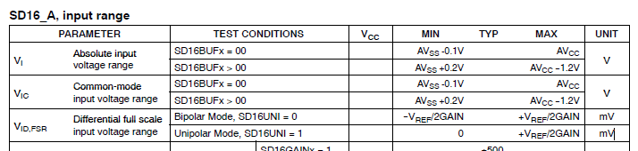
I'm measuring low-millivolt, low-frequency signals from two air-coil sensors using the SD16 ADC: gain of two, Fm = 1,048,576 Hz, 0SR = 128.

When connected differentially, with the coil returns grounded, the rms noise is about 2 ADC counts.  Unfortunately, I need to measure the coils separately.  When I configure channels 0 and 1 single-ended, with A- grounded, the noise increases dramatically, to 8-10 rms counts.

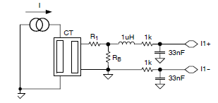
IF, rather than grounding A-, I connect the coil return to A- and ground A- through a ~1K resistor, the noise drops back to around 2 rms counts.

The 1K to ground degrades the anti-aliasing inputs, larger values would be better.

WHY does the SD16 hate grounded inputs, and WHAT is an appropriate range, if any, for the pseudo-ground resistor?

  • Michael Cushing said:
    WHY does the SD16 hate grounded inputs

    This is problem for any converter - ground noise. It is hard to fight ground noise especially if it is common for both digital and analog parts of your circuit. Actually differential measurements is best solution for your problem :)

    What you can do.. If you say that you measure low-frequency signal then use higher OSR values - to filter-out high frequency noise out of measurement. If your msp430 have separate, analog ground then take care of good coupling of it against digital ground - use quality coupling capacitors and use ferrite bead between analog and digital grounds. I am afraid - there shall be appnote from TI about PCB design of hi-precision ADC's - follow recommendations.

    Otherwise you have to look for msp430 having mode differential inputs or two delta-sigma ADC's.

  • Ilmars said:
    This is problem for any converter - ground noise.

    Indeed, GND noise can be a nuisance. However, with the coil return connected to A- and grounded through 1k, noise drops significantly, so it doesn't look too much like GND noise. But from the description, I have the suspicion that otherwise the coil has no relation to GND and therefore the A+ input is rather floating. In this case, GND is maybe just capacitively coupled, with much resulting noise.
    A true single-ended input signal has no voltage.

  • Jens-Michael Gross said:
    with the coil return connected to A- and grounded through 1k, noise drops significantly

    Because you are building RC filter out of 1k resistor and ADC input capacitance.

  • Ilmars said:
    Because you are building RC filter out of 1k resistor and ADC input capacitance.

    But the resistor is in parallel to the input capacitor. It only adds a load to the coil - and gives it a reference to GND.

    To form a low-pass with the input capacitance, the resistor would have to be in series with the capacitor. (which the 1k series resistance of the input multiplexer already does).
    Or a capacitor to GND would also form a low-pass (obviously)

  • Jens-Michael Gross said:
    But the resistor is in parallel to the input capacitor

    Just only one of two input capacitances. It is parallel to A- input capacitance but in series to A+ input of ADC. Don't forget about coil inductance and it's properties in case of high freq noise. it is quite complex filter, but still filter.

    [edit]  Thought again: if 1k resistor is connected to "noisy GND" then even for A- capacitor it is in series - for noise source.

  • Thank you - it remains a mystery.

    When acquiring from the coils differentially, I'm sure the ADC input "requires" a DC return, so the two coil hot ends go to A- and A+, and the two returns to to ground (Avss).  This gives the low noise figure, actually a little less than two, so that the SNR is very close to the theoretical 85 dB.

    When "attempting" to measure single-ended the hot end of the coil goes to A+ and the return goes to A-.  The problem occurs when the input is made single-ended by directly pulling A- to ground (the correct single-ended configuration), and the SNR drops to less than 70 dB.

    I tacked in the 1K resistor from A- to ground out of sheer frustration, and was amazed to find that something that should have made it much worse made it much better, back up to 85 dB again.

    Unfortunately, I don't think this is a real solution.  The real instrument operates in a high-voltage environment, around 100 KV, and I suspect the "pseudo-floating" A- will be very susceptible to induced noise.  I can't test it until we build the first prototype...

    (I really like the idea of forming an accidental low-pass filter, but I thought about the 2.5 pF input capacitance and realized the corner frequency would be around 60 MHz, which might not be too useful.)

  • I decided to make this a separate post, rather than including it in the previous reply to all of your fine suggestions.

    The reason I posed this as a potential SD16 problem, rather than a circuit design problem, comes from the SD16A description in the 4xx user guide.

    If you look at the introductory block diagram, the channel 5 Vcc monitoring input purposefully converts Vcc and ground to a differential input using the R-5R-R resistors, rather than a simple voltage divider.

    If this is what's necessary to get a low-noise signal, I'd like to know what the range for R is.  I suspect it's even more critical for the SD16, since it probably needs an on-board negative voltage generator to measure below ground.

    This has been a problem with the MSP430 since the very first 3xx series - they are very nice chips, but very poorly documented.  Compare the MSP data sheets with the DSP data sheets to see what I mean.

    But, the mystery remains.

  • Michael Cushing said:
    If you look at the introductory block diagram, the channel 5 Vcc monitoring input purposefully converts Vcc and ground to a differential input using the R-5R-R resistors, rather than a simple voltage divider.

    Because ADC is differential!

    Michael Cushing said:
    But, the mystery remains.

    Perhaps because you don't fully understand how differential ADC's work, what's advantages of them against single-ended. Your application asks for differential mode but you are trying to void all the gains of differential signal transmission and measurement by tying one input of differential ADC to ground. Delta-sigma ADC used in single-ended mode is actually crippled ADC. Those were first articles that popped-up:

    http://www.edn.com/design/analog/4332591/Maximize-performance-when-driving-differential-ADCs

    http://www.planetanalog.com/author.asp?section_id=510&doc_id=559191

    Pay attention to common mode noise rejection loss and dynamic range loss when one input tied to GND which probably are main two problems you got.

  • First; Maybe the LDC1000 Inductance to Digital Converter fits better to your needs.

    Second;

    Do you use an evaluation board, and which one, which MSP?

    How do you connect everything, using a breadboard?

    What are the voltages you want to measure at which gain, can you propose a schematic?


    The value of the resistors (normally) can be found in the device data sheet.

  • Ilmars, you're missing the point again.  I have two separate coils which need to be balanced (calibrated).  To save the money and noise of an external pot, we'd like to balance them digitally.  The differential input works perfectly, but doesn't allow one signal to be balanced to the other signal, since they're already mixed together.

    Therefore, we need two ADC inputs, one from each coil.  Then one of the coil inputs is multiplied by a calibration constant and the two inputs are added together.

    There is no dynamic range loss, since the two inputs are summed.

    The problem is, you can't just hook the two wires of a coil to the A+ and A- inputs, since there's no DC return path, so we end up needing a single-ended input.

    We may very well be talking about common mode noise rejection, but since it works with a 1k resistor to ground (pseudo-differential?), how come?

    As you're probably aware, you can always hook one differential input to a fixed potential and get an expected behavior.  In this case, we're getting an unexpected behavior.

  • Michael Cushing said:
    Ilmars, you're missing the point again.

    Whatever. Back to your application which honestly I don't understand. Maybe you tell what those two coils are doing/measuring, what you mean by saying "calibration", how your "ideal" circuit shall look like. Also why you say that signal from two coils is mixed together if they are just two coils, ideally floating against GND. - I do not get it. Perhaps schematics and more info about your device will shed the light.

    [edit] This one is interesting: "the two wires of a coil to the A+ and A- inputs, since there's no DC return path, so we end up needing a single-ended input.". DC coils or what?

  • Hi Ilmars, there are two separate answers:

    1)  Forget that they are coils and think of them as two separate signals from two sensors.  The final answer is the sum of the two signals, but due to manufacturing tolerances each sensor may be off by, say, +/-2%.  During calibration you determine that one sensor is 1.5% less than it should be, so each time you acquire the signal from that sensor you multiply it by 1.015 and it's calibrated.  Do a similar thing for the other sensor, then sum the two calibrated values.

    2)  To my knowledge, you can't apply a floating differential signal to differential ADC inputs.  For example, the SD16 spec says "Absolute input voltage range Avss - 1.0  to  Avcc".  That means the absolute value of the signal with respect to ground (Avss) cannot exceed those two voltages.

    If you hook up two wires from a sensor to the ADC input pins, what's the absolute voltage of that sensor compared to Avss?  It could be -10, or +7, or if you're really lucky, it could be between -1 and Avcc and it'll work.  So, what you need to do is to find some way to refer the sensor potential to Avss, and the most common way is to connect them with a wire.  The ADC guys tend to call that a "DC return" - it puts the signal into the correct absolute voltage range.

    So, if you're measuring differentially the hot wires go to the differential inputs and a return wire goes to Avss ground.  If you're measuring single-ended, the hot wire goes to, say, A+ and the return wire as well as A- goes to Avss ground.  That way you're measuring with respect to Avss.

  • Michael Cushing said:
    If you look at the introductory block diagram, the channel 5 Vcc monitoring input purposefully converts Vcc and ground to a differential input using the R-5R-R resistors, rather than a simple voltage divider.
    If this is what's necessary to get a low-noise signal, I'd like to know what the range for R is.  I suspect it's even more critical for the SD16, since it probably needs an on-board negative voltage generator to measure below ground.

    IMHO, the main reason for the R-5R-R approach is to keep the inputs away from VCC and GND, as any analog circuitry has problems when the input reaches the supply lines.
    With this divider, the input voltage is 5/7 of VCC (resistors can be very closely matched on a die even if their absolute values vary) and you will circumvent any nonlinearities due to saturation or offset.

    Michael Cushing said:
    This has been a problem with the MSP430 since the very first 3xx series - they are very nice chips, but very poorly documented.


    I found some part of the 3x family documentation rather more complete than the streamlined versions that came later. Especially the timer internals are better documented (and explain some oddities that are not explainable by the 'current' docs)

    Michael Cushing said:
    I have two separate coils which need to be balanced (calibrated).  To save the money and noise of an external pot, we'd like to balance them digitally.  The differential input works perfectly, but doesn't allow one signal to be balanced to the other signal, since they're already mixed together.

    Okay, that explains the scenario.

    You have two signals, A and B, where B is A*x during calibration. And you need to know x for calibration, so you can derive some information later by adding A and B*x. So you need to measure them separately.

    Are the sensor outputs floating? You could tie the negative side to a fixed, filtered and noise-free voltage. Like 1/2 Vref.
    Another approach is to send the CPU into LPM during the measurement, so it doesn't create any GND ripples..
    The resistor to GND is another possible way. Here you use the input capacitance as a low-pass filter, while providing a GND return path. Instead of 1k, 10k can be used as well. Since the ADC doesn't  work potential-free internally (the circuit is of course GND based), your consideration about the sensor voltage levels still apply, whether you have this GND resistor or not. Both sensors need to be either potential-free or on the same GND potential (signals not exceeding the MSP input voltage range)

    Some MSPs offer a separate AGND input which can be separately routed and filtered, to provide a ripple and noise free GND for analog parts.

    Michael Cushing said:
    In this case, we're getting an unexpected behavior.

    Are you? As I said, with the resistor, the input capacitance acts as low-pass filter. Don't forget that the ADC samples momentary snapshots of the input signal, so even high-frequency noise may count - and a filter with a high cutoff frequency can still make a difference.
    If you add the two single-ended sample results, does the noise cancel out?

  • Agree TI documentation (in general for all American companies) is not always easy to read, but if you don’t take a serious look to them you get one of these mistakes;

    Michael Cushing said:
    using the R-5R-R resistors

    It’s 5R-R-5R, which gives 300mV @ 3,3Vcc which is fully in the range of the VID and matches;

    Jens-Michael Gross said:
    keep the inputs away from VCC and GND, as any analog circuitry has problems when the input reaches the supply lines

  • Michael Cushing said:
    If you hook up two wires from a sensor to the ADC input pins, what's the absolute voltage of that sensor compared to Avss?  It could be -10, or +7, or if you're really lucky, it could be between -1 and Avcc and it'll work.

    OK, got it :) At last. Yes, to bring coil potential into GND to VCC range, easiest way is to tie them into GND. But not the best. Mainly because you have AC signal, right? If one end of coil is grounded then you lose negative period of your signal. Not to mention that you destroy main idea of differential ADC with all the consequences I already mentioned before.

    If it is ok to have some resistive load for coil (usually should be) - then you could possibly consider resistive bridge of equal resistors between VCC and GND, put your coil in a middle. One bridge per coil. You can add pot into one leg to trim balance and zero coil DC current - disconnect coil and trim bridge so between midpoints you measure zero voltage. Such way noise on GND or VCC or both will be equal to both A- and A+ inputs, thus will balance-out in differential mode of ADC operation. Also for best results use twisted-pair wires from coil to bridge, locate bridge as close as possible to ADC input, keep "+" and "-" traces parallel and equal length.

  • I think we can close this discussion - until I prove myself wrong, I'm going to accept that this is a common mode noise problem, since most everything else has been eliminated:

    *  I really don't think a low-pass filter at 60 MHz is going to fix anything;

    *  Since the inputs are specified from -1 to AVcc, ground is nowhere close to a rail;

    *  We don't lose the negative half of the cycle, since the input can go down to -1 volt.

    Here's my take on the common mode noise.  If we run the signal to A+ and A- and ground A-, ALL of the common-mode noise is going to appear at A+ and be amplified.  If, instead, we ground A- through a resistor R, some of the common-mode noise will appear at A- and be canceled.  The sort-of problem is that R has got to be a lot bigger than the source impedance to get the maximum cancellation, I guess a hundred times bigger to get 99% cancellation.

    (I apologize for my 5R-R-5R mistake - the manual was sitting right if front of me, and I typed it wrong!)

    (I agree with Jens-Michael.  The original 3x documentation (sometimes haltingly translated from German) really tried to tell you how a module worked, so you could use it to best advantage.  This entire discussion would have been entirely unnecessary with a little more documentation...)

    Thanks again, - Mike

  • Michael Cushing said:

    *  Since the inputs are specified from -1 to AVcc, ground is nowhere close to a rail;

    *  We don't lose the negative half of the cycle, since the input can go down to -1 volt.

    Which msp430? Those chips with SD16 I know - does not allow what you say:

  • Michael Cushing said:
    *  I really don't think a low-pass filter at 60 MHz is going to fix anything;

    3dB @60MHz is still some attenuation on 1MHz. Note that 1LSB on 16 bit ADC is -96dB. I agree, it won't be much, but definitely more than nothing.

    Michael Cushing said:
    *  Since the inputs are specified from -1 to AVcc, ground is nowhere close to a rail;

    Depends on the MSP you're using.

    Anyway, the MSP does not have a negative supply. GND is the 'negative rail'. Even though the electronics is built to circumvent this, there will still be nonlinearities or offsets around GND.

    Michael Cushing said:
    This entire discussion would have been entirely unnecessary with a little more documentation...

    True. Yet I guess that other discussions would arise. The 3x documentation was great for skilled people, but I guess that many newcomers did have problems filtering the basics form all this, to just make a start.

    The current users guides, maybe even a bit more stripped down to the essentials, and then extended by an 'internals' chapter for each module, would be really great.
    Well, as far as I can deduct these internals, I'll try to put them into my book.

  • (There are two SD16s - the SD16 and the SD16-A.  The SD16, which is what we're talking about, is clearly designed to handle bi-polar inputs and is specified from -1 to +Avcc.)

    Maybe we could extend this discussion.  The SD16 is a noisy beast.  I'm trying to replace some nice external analog circuitry with a single-chip solution to save cost, but it requires some really tricky tap-dancing to work around the noise.  I'm in the middle of trying to figure out one of the missing SD16 specifications, the voltage noise, en, and I'm having to make some assumptions I'm not sure about.  I'd appreciate some help.

    The voltage noise, in typewriter script, usually has units of rt/Hz, which means take the noise, usually in nV, and multiply it by the square root of the bandwidth to determine the expected rms noise.

    The only noise spec for the SD16 is SINAD, signal to noise and distortion, the distortion usually being the first five harmonics.  The first assumption I"m making is SINAD is approximately equal to SNR.  The spec for a gain of one is 85 dB with 1 MHz modulation frequency and OSR = 256.

    The second assumption I'm making is "1 MHz" is actually 1,048,576 Hz, a multiple of the watch crystal frequency.  The sampling rate then is 4,096 samples per second.  If you work through the sinc3 filter response, the -3 dB corner frequency is 1,070 Hz.  Using the rule of thumb that 1.57*Fc is the bandwidth, the bandwidth is 1,680 Hz.

    The test signal has amplitude 500 mV, so the rms signal is 500mV  / sqrt(2) = 353.6 mV.

    Solving SNR = 20 * log(Signal/Noise) for Noise, you get Noise = Signal / 10^(SNR/20) = 353.6 mV / 17,783 = 19.88 uV rms.

    Dividing the noise by the square root of the bandwidth we get en =19.88 uV / sqrt(1680 Hz) = 485 nv rt/Hz.

    As I suggested above, this is a horrible noisy beast - The 80 cent OP777s I'm trying to get rid of have en = 15 nv rt/Hz.

    Could somebody please do a sanity check and tell me if I've made a stupid assumption or an even stupider math error?  This en is a little hard to swallow...

    (I just did a quick test using the internal shorted-input channel 7 with Fm = 1,048,576, OSR = 256, gain = 1.  The noise was 0.79 rms counts (LSBs).  The SD16 resolution is 1.2 V / 2^16 = 18.3 uV per bit, so the noise is 0.79 * 18.3 uV = 14.5 uV rms.  This is a little bit better than specified, and corresponds to SNR = 88 dB.)

  • Michael Cushing said:
    There are two SD16s - the SD16 and the SD16-A.  The SD16, which is what we're talking about, is clearly designed to handle bi-polar inputs and is specified from -1 to +Avcc

    SD16 is kind of "special", I noticed it in some "energy meter msp430's", but have no experience with it (thanks god). Perhaps TI engineer can explain differences, but one is clear: they (energy meter ADC's) have unusual coupling circuit. Good news: you nearly copied it.

  • Ilmars,

    It's not really too special - if you look in the 4xx user's guide you will find one chapter on the SD16 and another chapter on the SD16-A.  Most of the energy chips are in the 2x family and they are called SD24 or SD24-A, but if you look at the specs they are just re-labeled SD16s (you CAN acquire 24 bits from all SD16s).

    The coupling circuit you show is just an anti-aliasing circuit (Fc = 4.8 kHz), except Rb is a burden resistor to match the output of the current transformer (CT) and the inductor is to reduce current spikes coming in from the power line.

  • Michael Cushing said:
    The coupling circuit you show is just an anti-aliasing circuit (Fc = 4.8 kHz), except Rb is a burden resistor to match the output of the current transformer (CT) and the inductor is to reduce current spikes coming in from the power line.

    Thank you for explaining, but I was talking just about GND-connected secondary and series 1k resistor connecting "-" input which you found as an ultimate solution for your problem ;) Good luck, I am off of this funny thread

  • Jens-Michael Gross,

    Your mentioning a book tickled my memories.  Way back in the late 1990's when the MSP430 was transferred from Germany to the US it was accompanied by several incredibly good manuals.

    The one that comes immediately to mind is the "MSP430 Family Mixed-Signal Application Reports", SLAA024, that is just filled with brilliant examples of how to use the MSP430 effectively.  I STILL remember the section on how to emulate a jump-if-positive (jp) instruction as being priceless.  The 48-bit integer square root routine that I use for RMS noise analysis is a (very slightly) expanded version of the example in this manual.

    Those manuals are carefully hidden way deep in the stack of literature, very difficult to get to.  If you want to find out how hard, try to search for one without remembering the full name or number, as I just did.

    There's two ways I can think of to program an MSP430: 1) Use assembly language to wring every bit of efficiency out of the chip that you can, ending up with a system that uses the lowest cost processor at the lowest speed possible to gain maximum battery life; or 2)  Use C and buy a more expensive processor and run at a higher speed to make up for inefficiencies.

    I'm way deep in approach #1 right now, trying to replace ten bucks of analog parts with a very noisy, power hog of an SD16, but at a very low cost.

    I'm wondering if you have any feelings for the direction embedded software development is taking, and if there might be differences between Germany and the US.

    And I guess I'm wondering if this is the right place to ask?

    Thank you, - Mike

  • Ilmars,

    I'm sorry, I was just trying to answer your question.  No, that wasn't the solution.  The actual solution was a resistor from what's called I1- to ground, and the secondary was not grounded but went to I1- (through an anti-aliasing circuit).

  • Michael Cushing said:
    The one that comes immediately to mind is the "MSP430 Family Mixed-Signal Application Reports", SLAA024

    Yes, it's quite good. And it's form 2000. However, it covers the 3x family only, so much of it is outdated information.
    My own book won't contain extensive coding examples, but rather textual descriptions of possible uses and pitfalls. On a less technical level (but without sparing the technical details).
    My hope is that it will help newbies to quickly get into it, while still providing in-depth information for more advanced MSP users.

    Michael Cushing said:
    Those manuals are carefully hidden way deep in the stack of literature, very difficult to get to.  If you want to find out how hard, try to search for one without remembering the full name or number, as I just did.

    I agree that the document management system used by TI, even if it may have some advantages, is far from being perfect. Convenient for the common use, but difficult if not impossible to use for advanced requests.
    The disappearance of older document revisions is a nuisance too. Especially before there was a revision history in revised documents (something I suggested some time ago).

    Michael Cushing said:
     Use C and buy a more expensive processor and run at a higher speed to make up for inefficiencies.

    Actually, the current C compilers are quite efficient. Sometimes, I used a compiled code as base for a streamlined assembly version. And for simpler tasks, I often found that there is nothing to optimize at all.

    I do quite complicated things on relatively small and slow 1x family processors in C. Only a few sections contain inline assembly to save a critical µs or to ensure that later code changes won't break the timing due to different optimization.

    Michael Cushing said:
    trying to replace ten bucks of analog parts with a very noisy, power hog of an SD16, but at a very low cost.

    Well, low price is one of the advantages of the MSP. Sure, the internal modules are no replacement for separate high-precision parts. But these often do cost more than the whole MSP. And are often not really required.

    Michael Cushing said:
    I'm wondering if you have any feelings for the direction embedded software development is taking

    A common '(d)evolution' is to use a generic high-speed ARM processor core and do all the things in software which could be better done in hardware. Well, maybe because so many students are taught to solve problems by algorithms rather than using their brain for an efficient approach that uses all possibilities.
    A bit like using Excel tables for project management while there is dedicated project management software available that can do the same job way more efficiently - once you have learned to use it properly.

    Michael Cushing said:
    and if there might be differences between Germany and the US.

    I don't think there are much differences between Germany and USA. Too many German companies have been swallowed by international corporate groups, so the typical company philosophy has been equalized on both sides of the ocean. Maybe on niche markets, with low-count high-price products (like the ones I design) there's still place for doing things 'right'

    Michael Cushing said:
    And I guess I'm wondering if this is the right place to ask?

    Why not? There's no dedicated social forum (only a social Blog), and asking for efficiency in programming surely belongs to the MSP corner as much as to any other - if not more (as efficiency is a key argument for using an MSP).

  • I was just looking at a lovely counter-example.  If you you're driving a 3 1/2 digit LCD (0000 to 1999), you usually need to convert binary to bcd.  The C idiom for this looks reasonably efficient, until you actually count the division cycles, and then it doesn't look too hot,

    for( index = 0; index < 4; index++ )             /* Convert four bcd digits */
                                                     /* Takes 1,201 cpu cycles */
    {
      bcdDigit[index] = number % 10;                 /* 151 cpu cycles */
      number          = number / 10;                 /* 146 cpu cycles */

    } /* End four bcd digits */

    What's even worse is most C libraries return both the quotient and the remainder, so it could run twice as fast, but you can't get to both from C.

    If you didn't know that the MSP430 is designed to handle bcd numbers (and the DADD instruction doesn't explicitly describe it), you miss this,

    ;
    ; Convert R12 to four binary-coded decimal (bcd) integers in R13.
    ;
        mov.w  #12, R14                          ;(2) Four digits < 2000 = 12 bits
        clr.w  R13                               ;(1) Clear the result
        rla.w  R12                               ;(1) Left justify the 12 bits
        rla.w  R12                               ;(1)
        rla.w  R12                               ;(1)
        rla.w  R12                               ;(1)
    bcdLoop:                                     ; Convert 12-bit binary to 16-bit bcd
        rla.w  R12                               ;(1) Binary MSB into carry
        dadd   R13, R13                          ;(1) Add bcd + carry
        dec.w  R14                               ;(1) Done?
        jnz    bcdLoop                           ;(2) No, continue

    As it sits, this takes 67 cpu cycles, which isn't too shabby, but the loop control is taking up 3/5 of the loop time.  If you don't mind unrolling the loop you get rid of the counter,

      REPT 12                                    ; Convert 12-bit binary to 16-bit bcd
        rla.w R12                                ;(1) Binary MSB into carry
        dadd R13, R13                            ;(1) Add bcd + carry
      ENDR

    and it now takes 31 cpu cycles, which is 40 times faster than C.  I timed the C routine with the IAR compiler on full optimization for speed, so it's pretty realistic.

    (If you want to know the full terrible story, I inherited the C version above, EXCEPT the numbers were being carried as floating point numbers, and cast to integer for each digit, so it was about four times slower than the already slow algorithm!)

  • Michael Cushing said:
    The C idiom for this looks reasonably efficient, until you actually count the division cycles,

    Great post about coding efficiency. It supports my plea to avoid divisions when possible (and floats too).

    Some time back, we had a similar situation where an int->ASCII conversion was required. Using a looped subtraction was way faster than using the usual sprintf (and much smaller than linking sprintf just for this). Even though it was done completely in C.

    BTW, the RTC_B/RTC_C modules provide a hardware 12 bit binary/BCD conversion. 6 cycles to convert a register from 12 bit binary to 16 bit BCD. No other registers clobbered.

  • Well, my original question was, roughly, "What's wrong with SD16 single-ended inputs?"  We eventually concluded that it must be sensor common-mode noise, and sort-of closed the thread.

    It turns out that was wrong - the SD16, at least on the '42x, does handle single-ended inputs horribly.

    Searching for a better alternative, I ended up with the SD24 in the '67xx family.  On the surface, it looks like a re-branded SD16 - same SNR, etc.  In reality, it's a far superior device, and meets all of the goals.

    With the SD16 when I took the sensor and connected it differentially, I got a certain amount of noise.  When I switched it to single-ended mode, the noise increased by a factor of four.

    With the SD24 at a gain of four I get about 450 rms counts of noise (using a signed 25-bit sample) when the sensor is attached in either differential OR single-ended mode.  That 450 counts corresponds to 8 uV rms, which is pretty respectable even when compared with many analog ADCs.

    - Mike

  • Michael Cushing said:
    It turns out that was wrong - the SD16, at least on the '42x, does handle single-ended inputs horribly.

    Surprising discovery! Thank you for letting us know. This once more reminds that if you are looking for performance - use standalone ADC.

  • No, the SD24 is the built-in ADC in several MSP families - it's not a separate ADC.

    The exact test is the SD24B in the MSP430F673x family.

  • Michael Cushing said:
    No, the SD24 is the built-in ADC in several MSP families - it's not a separate ADC.

    Yes I know. I did not mean SD24 but standalone ADC IC's as such.

**Attention** This is a public forum