This thread has been locked.

If you have a related question, please click the "Ask a related question" button in the top right corner. The newly created question will be automatically linked to this question.

MSP430FR5969 BSL Password

Other Parts Discussed in Thread: MSP430FR5969, MSP-TS430RGZ48C, MSP-FET, MSP430FR6989

I am trying to interface to the BSL usingthe UART communications and 2 GPIO ports on a linux micro to enter the BSL mode.

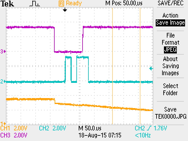
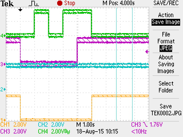
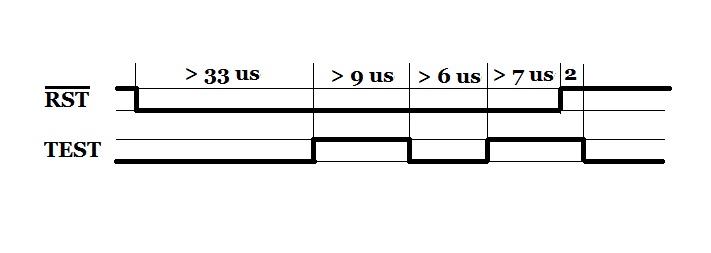
First problem I encountered was that providing the correct bit time patterns on the RESET/TEST pins did not enter BSL mode. Instead the user application program would always start after the reset. I have checked all GPIO pin voltage levels and have verified that the correct sequence on the RESET/TEST pins is as per specifications.

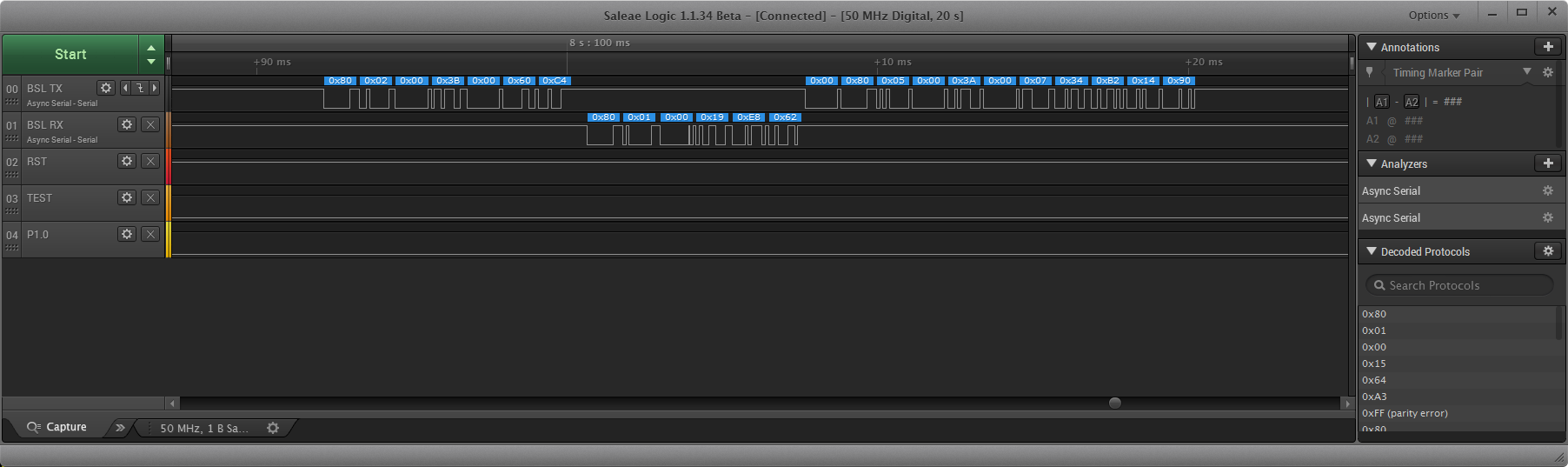
After unsuccessfully being able to enter BSL through using the external pins I forced a jump to the BSL entry point at 0x1000 in my user code and was able to get operation of the BSL.

After sending a Mass Erase command followed by the Password command (containing 32 x 0xFF) the BSL keeps doing a Mass Erase but will not unlock the BSL.

It does not matter how many times a send a Password command it will always do a Mass Erase.

I can confirm that the device is still locked by sending a TX BSL Version command and I get a response from the BSL that it is not unlocked.

I am able to successfully communicate with the BSL but I cannot unlock it.

I have read all the documentation several times and checked the Password command protocol but I am at a lose as to why it will not unlock. The documentation says that the password should be 32 x 0xFF after a Mass Erase and that is what I am sending ie:

0x80 0x21 0x00 0x11 0xFF 0xFF 0xFF 0xFF 0xFF 0xFF 0xFF 0xFF 0xFF 0xFF 0xFF 0xFF 0xFF 0xFF 0xFF 0xFF 0xFF 0xFF 0xFF 0xFF 0xFF 0xFF 0xFF 0xFF 0xFF 0xFF 0xFF 0xFF 0xFF 0xFF 0xFF 0xFF 0x9E 0xE6

After this command the TX line from the MSP430FR5969 goes low for 13mS and there is no other response.

All other commands sent will get a core message response with BSL locked (0x80 0x02 0x00 0x3B 0x04 CKL CKH).

Does anyone have any ideas?

  • Hi Dave,

    Needless to say, this is unexpected behavior. 

    Which derivative and Rev of the device are you using? Send the markings of the device if you don't know.

    Is this happening with more than 1 device and are you using your own board or a TI board?

    The only timing restriction on the entry sequence that I know is that the minimum time for pin states which must be 250ns. Did you try with different delays in the TEST/RESET lines? Can you send some screenshots of your entry sequence?

    Can you read the contents through JTAG and verify that the device was mass erased, and the BSL signatures are OK? Check the password at 0xFFE0-0xFFFF, and BSL signatures at 0xFF84-0xFF87,

    And if you can, please send some screenshots of the TX/RX lines when sending the commands. 

    Regards,

    Luis R

  • Hi Luis,

    The device I am using is MSP430FR5969 TI 44I F AEV1 G4.

    I have tried various different timing for the pin states and several devices. I am using the MSP-TS430RGZ48C board for development.

    Below is a screen shot of the BSL entry sequence. Trace 3 is the reset line and Trace 2 is the TEST pin. Trace 1 is the UART TX line.

    I have noticed that when I place a blank (new) device in the UART does not seem to be activated when I execute the BSL entry sequence and I cannot talk to the device. The only way I can talk to the BSL is to activate it from my application program.

    I am beginning to think that the device is not being erased when I issue the Mass Erase command and are thus unable to gain entry, but I still have no idea why I cannot activate BSL mode externally.

    Once the chip is programmed with my application code the UART is active but again the BSL entry sequence does not place the chip into BSL mode but my application program starts up after RESET goes high.

    I am using CCS V6 with the MSP-FET jtag device but I have not been able to figure out how to read the chip memory from the platform. The only options I have been able to use is the debug mode but that reprograms the chip before entry.

    Is there a way of reading the chip memory without going into the debug mode?

  • Hi Luis,

     I have solved my problem but probably need some clarification from you.

    I am now able to successfully enter the BSL mode externally and implement various commands including unlocking the BSL.

    To do this I had to change the timing of the RESET/TEST pin signals in order to enter BSL mode.

    Originally I uses these signals with about 10mS timing between the signals. After this did not work I tried going faster and using 25uS as shown above but this also did not work.

    I have now changed the timing so that these signals are 1 second between edges and now I have no problem with access to the BSL.

    The data sheet says that there must be a minimum of 250nS between these signals but I have never been any where near that close.

    Why do you think that I have to have such a long time between these signals?

    Below is my new timing:

  • Hi Dave,

    I was able to replicate the behavior with my board. I tried the following sequence and it worked, though:

    The main difference was the initial toggle of both RST+TEST. 

    I'll double-check this behavior with the team and file a bug if needed.

    I was also able to test some of the commands, but I didn't have any problems.

    Here's the mass erase:

    As you may already know, there's no response for Mass Erase. The device actually starts sending an ACK (0x00) but then it stops and the line goes high. 

    Then I send the blank password:

    And here's the rest of the response to the password command, followed by the TX_Version command:

    Regarding your previous question, you can try using FET-Pro430 lite from Elprotronic to read the contents of the device using a FET.

    Regards,

    Luis R

  • Hi Luis,
    Yes that sequence seems to work for us. We are now using 10mS timing for our RESET/TEST lines and get into the BSL without any problems.
    We also have no problems with unlocking and various other commands.
    Thank you for your help.
  • Hi Luis,

    I am facing similar problems with the MSP430FR5969 (on a launchpad). I am executing the BSL from a test application that only has the following:

    __disable_interrupt();

    ((void (*)())0x1000)(); // call bootstrap

    I get into the BSL ok and can communicate with the BSL.

    The problem I have is that the mass-erase command does not mass-erase the device. Also a subsequent blank-password command does not gain full access to the BSL (i.e. the BSL does not get unlocked).

    I am sending the exact same command bytes as shown in above screenshots. But I do not get the same response. On both the blank password as well as on the mass-erase command I get the start of the ack (line goes low and then high again).

    The only way for me to unlock the BSL is by sending the correct BSL password. However even after that the mass-erase does not work (it does not mass-erase the device)

    After unlocking I am able to reprogram the device via BSL.

    Are the problems with the mass-erase and blank password command being caused by the fact that I am calling the bootstrap via a software call?

    Now the user guide (slau367g, page 53) states that the two BSL signatures residing on memory locations 0xFF84 and 0xFF86 can be programmed such that an incorrect password will not erase the device but instead send a password error. Could it be that these signatures are not read or not read correctly when calling the BSL via a software call?

    I would like the mass-erase command to work as I need it to blank the device (also as a security measure).

    Any help very much appreciated.
  • Just to let you know I solved the problem. I am using CCS for my development and it has support for the Memory Protection Unit (MPU) build in. While getting the bootstrap to work at some point I tried segmenting the FRAM memory by using the MPU. Although I disabled all of that again I had left the 'enable MPU unit' checkbox in CCS checked. So the MPU unit was enabled before doing the software call to the BSL and it was handling the MPU settings such that segment 2 and 3 where set to read/execute but not write enable.
    Disabling the MPU unit in CCS configuration for this project solved the problem of the BSL mass-erase not working.

    Cheers,
    Alwin
  • Luis RC said:

    I was able to replicate the behavior with my board. I tried the following sequence and it worked, though:

    The main difference was the initial toggle of both RST+TEST. 

    I'll double-check this behavior with the team and file a bug if needed. ...

    While you are at it, I want to inform you that I found the timing requirements for MSP430FR6989 BSL entrance sequence are as follows:

    Michael Bolton39 tried this too. He says all those intervals have to be >69 us.
    e2e.ti.com/.../489621

**Attention** This is a public forum