This thread has been locked.

If you have a related question, please click the "Ask a related question" button in the top right corner. The newly created question will be automatically linked to this question.

MSP430FR6989, Unable to use FRAM2 with #pragma PERSISTENT

Other Parts Discussed in Thread: MSP430FR6989, MSP-EXP430FR6989

Hi,

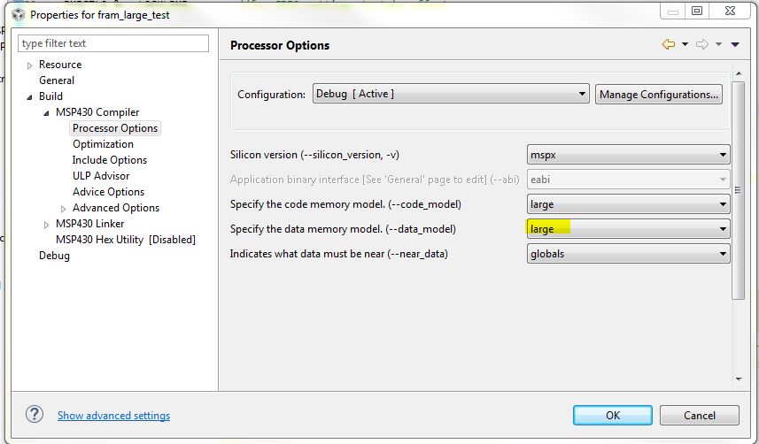
I'm using the MSP430FR6989 with 128kB of FRAM. For this project I'm planning on using the majority of the FRAM (~120kB) as data storage. I had just planned on using the #pragma PERSISTENT call to assign some large arrays to FRAM.

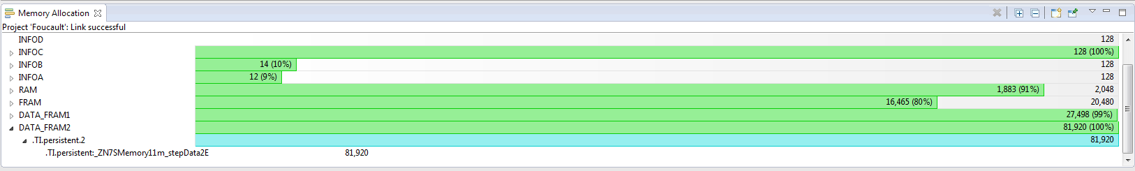
The problem that I am running into is that using the #pragma PERSISTENT only utilizes the first section of FRAM called "FRAM" in the linker file, which has a length of 0xBB80. There is a second section of FRAM in the linker file called FRAM2 that has a length of 0x14000 that I can't figure out how to utilize correctly.

Here is a snippet of the original linker file:

SECTIONS
{
    GROUP(READ_WRITE_MEMORY)
    {
       .TI.persistent : {}                  /* For #pragma persistent            */
       .cio           : {}                  /* C I/O Buffer                      */
       .sysmem        : {}                  /* Dynamic memory allocation area    */
    } PALIGN(0x0400), RUN_END(fram_rx_start) > 0x4400

    .cinit            : {}  > FRAM          /* Initialization tables             */

I tried modifying it so that it would hopefully use both FRAM and FRAM2

SECTIONS
{
    GROUP(READ_WRITE_MEMORY)
    {
//       .TI.persistent : {}                  /* For #pragma persistent            */
       .cio           : {}                  /* C I/O Buffer                      */
       .sysmem        : {}                  /* Dynamic memory allocation area    */
    } PALIGN(0x0400), RUN_END(fram_rx_start) > 0x4400

    .TI.persistent    : {}  > FRAM | FRAM2

    .cinit            : {}  > FRAM          /* Initialization tables             */

But even after modifying the linker, I can't get any data allocated to FRAM2. This is the error I keep getting:
"program will not fit into available memory. placement with alignment fails for section ".TI.persistent" size 0x176c0 . Available memory ranges: "

Any ideas on how to get this to work? Surely someone has used both of these FRAM sections for data storage!

  • Also, here are how the two FRAM sections are defined in the linker file:

        FRAM                    : origin = 0x4400, length = 0xBB80
        FRAM2                   : origin = 0x10000,length = 0x14000

  • Your data with the size of 0x0176C0 will not fit in either segment RAM (length 0x0BB80) or RAM1 (length 0x014000).

    You can try to make a continuous section by adding a “>” to the linker command line: “.TI.persistent : {} >> FRAM | FRAM2” but I’m not sure if this will work with a not continuous address space, otherwise you have to split your data over two memory sections, one using FRAM and the other using FRAM1.
  • Right, I think it is pretty apparent that I have to split the data between the two sections. My main question is how do I do that??

    I can't do it just using the PERSISTENT directive because that is what I am currently doing and it obviously won't split the data between the two locations.

    I don't think I can have my application write directly to either section without the risk of writing over any code/data placed there by the linker. Or is that not true? Whenever I try to write directly to one of those FRAM sections, the .map file doesn't reflect it:

    #define FRAM1_ADDR	0x4400
    
    uint8_t *p_FRAM1 = (uint8_t *)FRAM1_ADDR;
    
    for(i = 0; i < 2000; i++)
    {
        p_FRAM1[i] = 7;
    }

    Again, there's got to be a way to utilize the second section of FRAM (FRAM2). Anyone have any idea how?

  • You need to divide your memory space into (multiple) Sections for Code and Data. This can be done in the Linker Command file.

    Under MEMORY you can create a new, private, memory area, for example;
    My(F)RAM : origin = 0x0200, length = 0x0080
    Subtract the newly created memory area from the original one;
    (F)RAM : origin = 0x0280, length = 0x0180
    (these addresses and lengths are just an example)

    Under SECTIONS you create a new, private, section, and leave all others unchanged;
    MyRamSpace : {} > My(F)RAM

    Optional:
    MyRamSpace : type = NOINIT {} > My(F)RAM

    In your program you declare;
    #pragma DATA_SECTION (MyRamData, "MyRamSpace")
    char MyRamData[128];


    For more information see: “MSP430 Optimizing C/C++ Compiler” www.ti.com/.../slau132j.pdf.
  • Hi Leo,

    Thanks for the response and sorry for my long delay. I'm just getting back to this and tried out your suggestion. I'm finding that when I try to compile, though, that I get these warnings:

    #10015-D output file "Foucault.out" cannot be loaded and run on a target system Foucault C/C++ Problem

    <a href="file:/c:/ti/ccsv6/tools/compiler/dmed/HTML/17003.html">#17003-D</a> relocation from function "SMemory" to symbol "_ZN7SMemory10m_stepDataE" overflowed; the 17-bit relocated address 0x10000 is too large to encode in the 16-bit field (type = 'R_MSP430X_ABS16' (15), file = "./Services/SMemory.obj", offset = 0x0000001e, section = ".text:_ZN7SMemoryC1Ev") 

    Here are snippets from my updated linker file:

    MEMORY
    {
        TINYRAM                 : origin = 0x0006, length = 0x001A
        PERIPHERALS_8BIT        : origin = 0x0020, length = 0x00E0
        PERIPHERALS_16BIT       : origin = 0x0100, length = 0x0100
        RAM                     : origin = 0x1C00, length = 0x0800
        INFOA                   : origin = 0x1980, length = 0x0080
        INFOB                   : origin = 0x1900, length = 0x0080
        INFOC                   : origin = 0x1880, length = 0x0080
        INFOD                   : origin = 0x1800, length = 0x0080
        FRAM                    : origin = 0x4400, length = 0xBB80
    //  FRAM2                   : origin = 0x10000,length = 0x14000
        DATA1                   : origin = 0x10000,length = 0x14000
        JTAGSIGNATURE           : origin = 0xFF80, length = 0x0004, fill = 0xFFFF
        BSLSIGNATURE            : origin = 0xFF84, length = 0x0004, fill = 0xFFFF
        IPESIGNATURE            : origin = 0xFF88, length = 0x0008, fill = 0xFFFF
        INT00                   : origin = 0xFF90, length = 0x0002
        INT01                   : origin = 0xFF92, length = 0x0002
    .
    .
    .
    .
    }

    SECTIONS
    {
        GROUP(RW_IPE)
        {
            GROUP(READ_WRITE_MEMORY)
            {
               .TI.persistent : {}              /* For #pragma persistent            */
               .cio           : {}              /* C I/O Buffer                      */
               .sysmem        : {}              /* Dynamic memory allocation area    */
            } PALIGN(0x0400), RUN_START(fram_rw_start)
    
            GROUP(IPENCAPSULATED_MEMORY)
            {
               .ipestruct     : {}              /* IPE Data structure                */
               .ipe           : {}              /* IPE                               */
               .ipe_const     : {}              /* IPE Protected constants           */
               .ipe:_isr      : {}              /* IPE ISRs                          */
               .ipe_vars      : type = NOINIT{} /* IPE variables                     */
            } PALIGN(0x0400), RUN_START(fram_ipe_start) RUN_END(fram_ipe_end) RUN_END(fram_rx_start)
        } > 0x4400
    
        .cinit            : {}  > FRAM          /* Initialization tables             */
        .pinit            : {}  > FRAM          /* C++ Constructor tables            */
        .init_array       : {}  > FRAM          /* C++ Constructor tables            */
        .mspabi.exidx     : {}  > FRAM          /* C++ Constructor tables            */
        .mspabi.extab     : {}  > FRAM          /* C++ Constructor tables            */
        .const            : {} >> FRAM          /* Constant data                     */
        .text:_isr        : {}  > FRAM          /* Code ISRs                         */
        .text             : {} >> FRAM          /* Code                              */
    
        StepDataSpace     : {} > DATA1          /* Step data storage                 */

    .
    .
    .
    .
    }

    Basically, I designated all of FRAM2 to my new area called DATA1. I then assigned my new section, StepDataSpace, to DATA1. I also removed all other uses of FRAM2 so that there isn't a conflict. Then, in my source code, I declare an array that is suppose to be allocated to the new StepDataSpace:

    #define STEP_DATA_BUF_SIZE_BYTES 10
    
    /**
     * Initialize static member variables
     */
    #pragma DATA_SECTION("StepDataSpace")
    uint8_t SMemory::m_stepData[STEP_DATA_BUF_SIZE_BYTES] = {0};

    Any thoughts on why I'm getting these compiler warnings??
    Thanks!

  • Hi Leo,

    Thanks for the response and sorry for my long delay. I'm just getting back to this and tried out your suggestion. I'm finding that when I try to compile, though, that I get these warnings:

    #10015-D output file "Foucault.out" cannot be loaded and run on a target system Foucault C/C++ Problem

    <a href="file:/c:/ti/ccsv6/tools/compiler/dmed/HTML/17003.html">#17003-D</a> relocation from function "SMemory" to symbol "_ZN7SMemory10m_stepDataE" overflowed; the 17-bit relocated address 0x10000 is too large to encode in the 16-bit field (type = 'R_MSP430X_ABS16' (15), file = "./Services/SMemory.obj", offset = 0x0000001e, section = ".text:_ZN7SMemoryC1Ev") 

    Here are snippets from my updated linker file:

    MEMORY
    {
        TINYRAM                 : origin = 0x0006, length = 0x001A
        PERIPHERALS_8BIT        : origin = 0x0020, length = 0x00E0
        PERIPHERALS_16BIT       : origin = 0x0100, length = 0x0100
        RAM                     : origin = 0x1C00, length = 0x0800
        INFOA                   : origin = 0x1980, length = 0x0080
        INFOB                   : origin = 0x1900, length = 0x0080
        INFOC                   : origin = 0x1880, length = 0x0080
        INFOD                   : origin = 0x1800, length = 0x0080
        FRAM                    : origin = 0x4400, length = 0xBB80
    //  FRAM2                   : origin = 0x10000,length = 0x14000
        DATA1                   : origin = 0x10000,length = 0x14000
        JTAGSIGNATURE           : origin = 0xFF80, length = 0x0004, fill = 0xFFFF
        BSLSIGNATURE            : origin = 0xFF84, length = 0x0004, fill = 0xFFFF
        IPESIGNATURE            : origin = 0xFF88, length = 0x0008, fill = 0xFFFF
    SECTIONS
    {
        GROUP(RW_IPE)
        {
            GROUP(READ_WRITE_MEMORY)
            {
               .TI.persistent : {}              /* For #pragma persistent            */
               .cio           : {}              /* C I/O Buffer                      */
               .sysmem        : {}              /* Dynamic memory allocation area    */
            } PALIGN(0x0400), RUN_START(fram_rw_start)
    
            GROUP(IPENCAPSULATED_MEMORY)
            {
               .ipestruct     : {}              /* IPE Data structure                */
               .ipe           : {}              /* IPE                               */
               .ipe_const     : {}              /* IPE Protected constants           */
               .ipe:_isr      : {}              /* IPE ISRs                          */
               .ipe_vars      : type = NOINIT{} /* IPE variables                     */
            } PALIGN(0x0400), RUN_START(fram_ipe_start) RUN_END(fram_ipe_end) RUN_END(fram_rx_start)
        } > 0x4400
    
        .cinit            : {}  > FRAM          /* Initialization tables             */
        .pinit            : {}  > FRAM          /* C++ Constructor tables            */
        .init_array       : {}  > FRAM          /* C++ Constructor tables            */
        .mspabi.exidx     : {}  > FRAM          /* C++ Constructor tables            */
        .mspabi.extab     : {}  > FRAM          /* C++ Constructor tables            */
        .const            : {} >> FRAM          /* Constant data                     */
        .text:_isr        : {}  > FRAM          /* Code ISRs                         */
        .text             : {} >> FRAM          /* Code                              */
    
        StepDataSpace     : {} > DATA1          /* Step data storage                 */

    Basically, I designated all of FRAM2 to my new area called DATA1. I then assigned my new section, StepDataSpace, to DATA1. I also removed all other uses of FRAM2 so that there isn't a conflict. Then, in my source code, I declare an array that is suppose to be allocated to the new StepDataSpace:

    #define STEP_DATA_BUF_SIZE_BYTES 10
    
    /**
     * Initialize static member variables
     */
    #pragma DATA_SECTION("StepDataSpace")
    uint8_t SMemory::m_stepData[STEP_DATA_BUF_SIZE_BYTES] = {0};

    Any thoughts on why I'm getting these compiler warnings??
    Thanks!

  • Hi Robert,

    I am going to look into this to try to get you a good solution, and will try to reply back soon. Sorry to hear of your difficulties.

    Regards,
    Katie
  • Hi Robert,

    Here is the solution that I came up with (I may have to split into a couple posts because there is a lot):

    I modified the linker file attached:https://e2e.ti.com/cfs-file/__key/communityserver-discussions-components-files/166/lnk_5F00_msp430fr6989_5F00_modified.cmd

    Note, I'm using a newer version of CCS (6.1.1.00022) than you I think because my linker file (version 1.180 in the comments at top of linker file) looked a little newer than yours to start with. You may want to make sure to check for updates to make sure this works the way I'm telling you....

    Assumptions that I made: that you don't need to use IP Encapsulation, but should still use the MPU to protect against errant writes.

    Here's a list of what I modified in the linker file/key features:

    1) MEMORY portion of linker file

        INFOD                   : origin = 0x1800, length = 0x0080
        //FRAM                    : origin = 0x4400, length = 0xBB80
        //NEW
        //need 0xA000 below 0x10000 boundary for our data
        //and needs to be AFTER FRAM for code (for MPU grouping)
        //also need 0x400 boundary (granularity of MPU) so have to
        //add a little to DATA_FRAM to accomodate this
        FRAM                    : origin = 0x4400, length = 0x1800
        DATA_FRAM				: origin = 0x5C00, length = 0xA380
        //END NEW
        FRAM2                   : origin = 0x10000,length = 0x14000
        JTAGSIGNATURE           : origin = 0xFF80, length = 0x0004, fill = 0xFFFF
        BSLSIGNATURE            : origin = 0xFF84, length = 0x0004, fill = 0xFFFF
        IPESIGNATURE            : origin = 0xFF88, length = 0x0008, fill = 0xFFFF

    I modified the FRAM segment into two segments, FRAM (for code, consts) and DATA_FRAM (which will be for read/write data). Note we're going to use all of FRAM2 for read/write data too, but we don't need to do anything to this segment to do that.

    The way I set the boundaries for DATA_FRAM - your code needs 120kB of FRAM for read/write correct? That's 0x1E000. FRAM2 is from 0x10000-0x24000 so it can hold 0x14000 of this. That leaves 0xA000 that needs to go in DATA_FRAM. Now, FRAM originally went from 0x4400 to 0xFF80 (this is because 0xFF80-0xFFFF is used for JTAG password and interrupt vector table). We can't simply set DATA_FRAM from 0x5F80-0xFF80 because of the MPU. The MPU (memory protection unit) in the device is something that you want to have enabled in your project, because FRAM is so easy to write to (just like RAM) that you want to have a way to prevent you from accidentally overwriting your code - MPU controls memory access management. It only has granularity of 0x400 bytes for its boundary setting. So I chose the next closest 0x400 byte aligned boundary that would still fit our 0xA000 of data, 0x5C00. So DATA_FRAM will go from 0x5C00-0xFF80. The reason I'm putting DATA_FRAM after FRAM is because I want all of my read-write accessible memory to be in a block together, again because of the MPU (the MPU only has 3 segments that it can set different access writes to, so you want to keep similar data together.)

    2)SECTIONS portion of linker file

    SECTIONS
    {
    //NEW
    //  GROUP(RW_IPE)
    //    {
            GROUP(READ_WRITE_MEMORY)
            {
               //.TI.persistent : {}              /* For #pragma persistent            */
               .cio           : {}              /* C I/O Buffer                      */
               .sysmem        : {}              /* Dynamic memory allocation area    */
            } PALIGN(0x0400) > DATA_FRAM, RUN_START(fram_rw_start) RUN_START(fram_rx_end)
    
           //GROUP(IPENCAPSULATED_MEMORY)
           //{
           //   .ipestruct     : {}              /* IPE Data structure                */
           //   .ipe           : {}              /* IPE                               */
           //   .ipe_const     : {}              /* IPE Protected constants           */
           //   .ipe:_isr      : {}              /* IPE ISRs                          */
           //   .ipe_vars      : type = NOINIT{} /* IPE variables                     */
           // } PALIGN(0x0400), RUN_START(fram_ipe_start) RUN_END(fram_ipe_end) RUN_END(fram_rx_start)
    //    } > 0x4400
        .TI.persistent : {} >> DATA_FRAM | FRAM2         /* For #pragma persistent            */
    //END NEW
        .cinit            : {}  > FRAM          /* Initialization tables             */

    Here I made many changes. First, I completely commented out the IPE definitions because I assumed you will not be using these, just to make things simpler. Then I took .TI.persistent out of the READ_WRITE_MEMORY group that contains some sections you'd want in read/write FRAM like .cio or .sysmem (you may need to adjust your linker file MEMORY section to have more space if you use these FYI, but my simple program didn't need any of this - I think you'll only have things in those sections if you use sdtio funcs like printf or dynamic memory allocation like malloc, which I usually avoid).  I set fram_rx_end to be the address of where the read write memory starts this is for the MPU which I'll discuss more later - basically we do this because we're placing our read/write fram segment after our read/execute memory segment. This definition of fram_rx_end will be used later when setting up the MPU.

    I put .TI.persistent outside of this and set it to be placed in DATA_FRAM and FRAM2. Use >> so that it can split up the data between both sections as needed.

    #ifndef __LARGE_DATA_MODEL__
        .text             : {} >> FRAM          /* Code                              */
    #else
    //NEW
        //.text             : {} >> FRAM2 | FRAM  /* Code                              */
        .text             : {} >> FRAM  /* Code                              */
    //END NEW
    #endif

    I made it so that FRAM2 will not be used for code (.text) at all, even in large memory model because we need all of it for our read-write data in our case.

    3) MPU/IPE specific memory segment definitions

    First, I commented out all of the IPE definitions from #ifdef _IPE_ENABLE through the #endif that goes with it.

    For the MPU setup, I made some modifications - by default, the original linker file was putting all read-write memory at the very beginning of memory starting at 0x4400. In our setup, we are putting all of our read-write memory at the end of memory instead. So MPU changes are needed.

       // Segment definitions
       #ifdef _MPU_MANUAL // For custom sizes selected in the GUI
          mpu_segment_border1 = _MPU_SEGB1 >> 4;
          mpu_segment_border2 = _MPU_SEGB2 >> 4;
          mpu_sam_value = (_MPU_SAM0 << 12) | (_MPU_SAM3 << 8) | (_MPU_SAM2 << 4) | _MPU_SAM1;
       #else // Automated sizes generated by Linker
          /*#ifdef _IPE_ENABLE //if IPE is used in project too
             //seg1 = any read + write persistent variables
             //seg2 = ipe = read + write + execute access
             //seg3 = code, read + execute only
             mpu_segment_border1 = fram_ipe_start >> 4;
             mpu_segment_border2 = fram_rx_start >> 4;
             mpu_sam_value = 0x1573; // Info R, Seg3 RX, Seg2 RWX, Seg1 RW
          #else*/
             /*mpu_segment_border1 = fram_rx_start >> 4;
             mpu_segment_border2 = fram_rx_start >> 4;
             mpu_sam_value = 0x1513; // Info R, Seg3 RX, Seg2 R, Seg1 RW*/
             //NEW
             mpu_segment_border1 = fram_rx_end >> 4;
             mpu_segment_border2 = fram_rx_end >> 4;
             mpu_sam_value = 0x1315; // Info R, Seg3 RW, Seg2 R, Seg1 RW
             //END NEW
          //#endif

    I commented out some definitions related to IPE again here (you need to adjust your MPU boundaries if using IPE too). Then instead of setting the mpu_segment_border1 and 2 to be at fram_rx_start, which would normally be after our read-write memory and before our read execute memory, we instead need to set the borders to fram_rx_end because in our case we are putting the read write memory after the read execute memory.

    Finally, the mpu_sam_value needs to change to change the access rights for the MPU segments. In the original, segment 3 (end of memory) was rx access, and segment 1 (beginning of memory) was rw access. We need to flip this so that segment 3 is rw access and segment 1 is rx access. This is basically the value that will be written into the MPUSAM register in the device, so see the user's guide www.ti.com/lit/pdf/slau367 figure 7-10 to see the register bits and their meanings.

    This describes all the changes I made to the linker file - the next post will describe the c file and project setup.

    Regards,

    Katie

  • Here are the project changes I had to make:

    I used this c file as my test code:

    #include <msp430.h> 
    
    //(120kB = 0x1E000) set aside for storage of data in 2 sections
    //will have to have some above and some below the 0x10000 boundary
    //0x14000 space available above 0x10000
    //means need A000 space below 0x10000 for rest of the 120kB
    //below boundary
    #pragma PERSISTENT(myData1)
    unsigned char myData1[0xA000] = {0};
    //above boundary
    #pragma PERSISTENT(myData2)
    unsigned char myData2[0x14000] = {0};
    
    /*
     * main.c
     */
    int main(void) {
        WDTCTL = WDTPW | WDTHOLD;	// Stop watchdog timer
    
        P1DIR |= BIT0;
        P1OUT |= BIT0;
        PM5CTL0 &= ~LOCKLPM5; 		//for GPIO settings to take effect
    	
        unsigned char i = 0;
    
    	while(1)
    	{
    		P1OUT ^= BIT0;			//blink the LED
    
    		//some nonsense code to keep compiler from optimizing out arrays,
    		//would be your actual program here instead
    		//using __data20_write_char and __data20_read_char intrinsics
    		//because of data being at 20 bit addresses. See www.ti.com/lit/pdf/slau132
    		//myData1[i] = myData2[i]+ 1;
    		__data20_write_char((unsigned long int)myData1 + i, __data20_read_char((unsigned long int)myData2 + i) + 1);
    		//myData2[i] = myData1[i];
    		__data20_write_char((unsigned long int)myData2 + i, __data20_read_char((unsigned long int)myData1 + i));
    		i++;
    
    		__delay_cycles(50000); 	//delay for LED blink
    	}
    }
    

    It doesn't really do anything meaningful, it just writes to the large arrays that I made and placed in the persistent area of memory.

    Key features:

    1) Define arrays for your read-write memory where you'll be logging data, and use the PERSISTENT pragma to get them placed in the correct section of the linker file.

    //(120kB = 0x1E000) set aside for storage of data in 2 sections
    //will have to have some above and some below the 0x10000 boundary
    //0x14000 space available above 0x10000
    //means need A000 space below 0x10000 for rest of the 120kB
    //below boundary
    #pragma PERSISTENT(myData1)
    unsigned char myData1[0xA000] = {0};
    //above boundary
    #pragma PERSISTENT(myData2)
    unsigned char myData2[0x14000] = {0};

    I split it into two arrays - this is because there's not enough room for all of it in just FRAM2 or just DATA_FRAM. The linker won't split a contiguous array, so I did it here. I have one array that's 0x14000 bytes which should fit in FRAM2, and one that's 0xA000 which is the remainder of the 120kB that wouldn't fit in FRAM2 - that will end up in DATA_FRAM.

    2) When reading/writing to 20-bit addresses, you need to use some special intrinsics so that the compiler will generate the correct assembly. This doesn't usually come up because usually variables are in the lower 16-bit area of memory, in RAM, or the default location for read-write FRAM in lower memory.

    		//some nonsense code to keep compiler from optimizing out arrays,
    		//would be your actual program here instead
    		//using __data20_write_char and __data20_read_char intrinsics
    		//because of data being at 20 bit addresses. See www.ti.com/lit/pdf/slau132
    		//myData1[i] = myData2[i]+ 1;
    		__data20_write_char((unsigned long int)myData1 + i, __data20_read_char((unsigned long int)myData2 + i) + 1);
    		//myData2[i] = myData1[i];
    		__data20_write_char((unsigned long int)myData2 + i, __data20_read_char((unsigned long int)myData1 + i));
    		i++;

    The intrinsics for __data20_write_char, __data20_read_char, and similar intrinsics for reading/writing ints and longs, are all defined in the compiler guide www.ti.com/lit/pdf/slau132 Table 6-5.

    3) You need to set a few project properties to support the way we are using memory.

    MPU setup:

    Go to Project > Properties > General. There is an MSP430 MPU tab. By default, it will have "Enable Memory Protection Unit (MPU)" checked, and the radio button set to "Let compiler handle memory partitioning, associated access rights, and linker output section placemant". Leave it this way - this will make sure you have the MPU being used. All the changes we made in the linker file before will allow us to simply use this default setting. If we hadn't done some of the changes with the #defines for MPU at the end of the linker file, you'd end up having to select to manually specify the memory segments here instead and set everything correctly (that is another option, but as long as we were having to change the linker file I figured it would be best to just do it all there anyway).

    large data/memory model:

    In Project > Properties > MSP430 Compiler > Processor Options, select it as shown below:

    By default, it was probably set to large code model but restricted data model. I changed it to large data model since we are going to be writing to the 20-bit space for our data.

    Click OK after setting all of these and build the project.

    NOTE: it will take a long time to build the very first time most likely, because it will have to build all of the compiler run-time support libraries for the large data model that you just chose. Every time after this, it should build much faster. It may take several minutes the first time, so don't give up and stop the build - it will be better every time after that.

    The project should now build and be able to run. I think you should be able to follow something similar with your own project, and hope this helps give you a framework to get started.

    Just as a note about why you are having to make all these modifications to the linker file - the linker files were designed to by default support most common cases - it puts the persistent memory in lower memory because this is usually easier (e.g. don't have to use the __data20 intrinsics) and for many applications there is enough space for this to work. However, when you need something more custom for a particular application like yours which needs a large amount of data area, it can start to require customization of the linker files because the default case can't cover every usage.

    Please let me know if you have any issues with this or more questions about how it all works.

    Regards,

    Katie

  • Would you mind sharing a little bit of information about what kind of application this is (if you can talk about it)? I'm assuming you are doing some sort of data logging - we always love to know what types of applications people are using FRAM for!
    -Katie
  • Katie,

    Thank you so much for such a detailed and helpful response! I don't think I've ever received such a helpful response as this one. I do have one question. I may end up changing the amount of memory reserved for data storage, but I went ahead and tried compiling with the ranges you had outlined in your example.

    The problem I run into is if I allocate my two data buffers as you had done in your c file (one at 0x14000, and the other at 0xA000), I get errors saying that the code is too large to fit into memory. If, however, I subtract 0x400 from 0xA000 (0x9F80) and use that, it uses up every last bit of memory in DATA_FRAM:

    #define STEP_DATA_BUF_1_SIZE_BYTES  0x9F80
    #define STEP_DATA_BUF_2_SIZE_BYTES  0x14000
    
    #pragma PERSISTENT
    uint8_t SMemory::m_stepData1[STEP_DATA_BUF_1_SIZE_BYTES] = {0};
    #pragma PERSISTENT
    uint8_t SMemory::m_stepData2[STEP_DATA_BUF_2_SIZE_BYTES] = {0};

    My question is, what is using that extra 0x400 bytes? When I look at the memory allocation gui, there's nothing in there taking up those 0x400 bytes. My only thought is that I am using C++ and perhaps that is a factor?

    Let me know what you think and thanks again!

  • Hi Robert,

    I'm glad to hear that you found it helpful, and hopefully by posting it here will help others in a similar situation in the future too.

    I had not noticed you were using C++, so I went back to see if I reproduce the same issue - I did not at first. Then I remembered the two other sections that I mentioned that are stored in the read-write area of FRAM in the DATA_FRAM section - remember this from the linker file:

            GROUP(READ_WRITE_MEMORY)
            {
               //.TI.persistent : {}              /* For #pragma persistent            */
               .cio           : {}              /* C I/O Buffer                      */
               .sysmem        : {}              /* Dynamic memory allocation area    */
            } PALIGN(0x0400) > DATA_FRAM, RUN_START(fram_rw_start) RUN_START(fram_rx_end)
    

    Does your code use stdio.h, like printf? If so, then this .cio section would be getting initialized and taking up some space. If you look in your Debug folder, open the .map file and do a search for .cio and for .sysmem. For me, as soon as I added #include <stdio.h> and a printf() statement to my project I started seeing the same issue you did, with 0x400 bytes not fitting. For me, my map file showed:

    .cio       0    00005c00    00000120     UNINITIALIZED
                      00005c00    00000120     rts430x_lc_ld_eabi.lib : trgmsg.obj (.cio)
    
    .sysmem    0    00005d20    000000a0     UNINITIALIZED
                      00005d20    00000008     rts430x_lc_ld_eabi.lib : memory.obj (.sysmem)
                      00005d28    00000098     --HOLE--

    You can see that .cio is placed at the beginning of DATA_FRAM - it needs to be, because it of course needs to be read-write memory. It is taking up 0x120 bytes for this buffer for the printf support. In addition, you can see that it also added space to .sysmem 0xA0 bytes = 160 bytes. This is the heap - you can find in Project > properties > MSP430 Linker > Basic options the heap size is 160 for dynamic memory allocation. 

    So in your project, check your map file for these two sections (.cio and .sysmem), and adjust your linker file size accordingly. Or don't use printf if you don't have to (we usually recommend avoiding stdio functions in general because they take up a lot of space and resources, which you can usually do more efficiently for an embedded app like this).

    Now, the reason that an entire 0x400 bytes is being added is because you can see that the linker file is set to the the READ_WRITE_MEMORY start at a section aligned to 0x400 - this was because we need to make sure whatever address we use for the start of DATA_FRAM, it needs to be aligned to a 0x400 byte boundary for the MPU border-setting to work out correctly. You could take out this PALIGN 0x400, but just need to make sure when you define DATA_FRAM manually that you align it to a 0x400 byte boundary.

    So 3 different options to get around this, depending on your situation:

    1) make DATA_FRAM 0x400 bytes longer when you define it at the top of the linker file
    OR
    2) don't use stdio functions
    OR
    3) place .cio and .sysmem in RAM instead of FRAM (assuming you are having enough extra RAM in your application?) You can do this by changing the linker file - move .cio and .sysmem outside of the GROUP(READ_WRITE_MEMORY) and set them to go into RAM instead:

            GROUP(READ_WRITE_MEMORY)
            {
               //.TI.persistent : {}              /* For #pragma persistent            */
              // .cio           : {}              /* C I/O Buffer                      */
               //.sysmem        : {}              /* Dynamic memory allocation area    */
            } PALIGN(0x0400) > DATA_FRAM, RUN_START(fram_rw_start) RUN_START(fram_rx_end)
               .cio           : {}    > RAM          /* C I/O Buffer                      */
               .sysmem        : {}    > RAM          /* Dynamic memory allocation area    */

    If you do option 3, then for sure the only things in DATA_FRAM are things you defined as PERSISTENT.

    Regards,

    Katie

  • Hi Katie,

    If I move .cio and .sysmem to RAM like your 3rd suggestion, everything works fine. That seemed to solve it, but I have a few clarifying questions.

    I don't actually use any stdio functions or any heap. My map file shows that .cio is 0 bytes and that .sysmem is 8 bytes. Those 8 bytes are the same 8 bytes shown in your attached map file. The thing is if I set my array size to the length of DATA_FRAM - 8 to account for those 8 bytes, I would expect it to fit within the 0x400 byte boundary. But that doesn't seem to be the case.

    Your comment about DATA_FRAM needing to be on a 0x400 byte boundary makes sense, but in your original example, we already manually set it to start at a 0x400 byte boundary, so that seems to be ok.

    Do you have any thoughts on why I can't just adjust my array size to be the length of DATA_FRAM - 8 instead of DATA_FRAM - 0x400?
  • Nevermind Katie, I figured out the answer to that last question. I see that an extra 1024 bytes is being allocated just for the 8 bytes used by .sysmem.
  • Right - that was because it was inside that group that had specified PALIGN 0x400 before. Now that you've taken it out and put the cio and sysmem in RAM, it shouldn't happen.

    There may be some other functions that use .sysmem or .cio - that would probably be more of a question for the (Missing Forum) because I'm not sure of all things that might use these sections. Putting the sections in RAM should be a pretty efficient solution for you if only 8 bytes are really needed for .sysmem right now.

    -Katie
  • Hi Katie,

    The custom linker file I have been using has worked great so far. However, I am having a new issue. For the extended address range, I have declared a single uint8_t array (m_stepData2) as PERSISTENT and set its length so that it occupies all of the space from 0x10000 - 0x24000.

    #define STEP_DATA_BUF_2_SIZE_BYTES  0x14000U
    
    #pragma PERSISTENT
    uint8_t SMemory::m_stepData2[STEP_DATA_BUF_2_SIZE_BYTES] = {0};


    I also have a function called WriteStepData that writes to this array. When testing in my debug build with the optimization level set to 0, everything works fine and if I look in the Memory Allocation GUI I can see that m_stepData2 is taking up all of the DATA_FRAM2 segment we declared in the linker:

    The problem I have now is if I change the optimization level from 0 to level 4 (Whole Program Optimizations), my calls to WriteStepData result in this warning:

    I seem to have narrowed it down to changing the optimization level that generates this warning. The problem is that I need to be able to use a high level of optimization to reduce the code size to a manageable level. 

    Do you have any insight into how I can still use the extended address space AND still keep the optimization level 4 enabled?

  • Hi Robert,

    Unfortunately this one goes outside my personal expertise a bit, as I don't know much about how the compiler does its optimizations at different levels. I would strongly recommend posting this one in the (DO NOT USE) TI C/C++ Compiler - Forum (make sure to provide a link back to this thread so that they can have some context about what you are doing). They will probably be able to give you some better advice about the differences between the optimization levels and what might be happening in your case.

    If you post it there, please put a link in this thread too for anyone coming upon this thread later (and I'll probably go subscribe to the other thread to make sure you get help and learn something new myself).
     
    Regards,
    Katie

  • Hi Katie,

    This thread was super helpful for what we were wanting to do. But I have some questions for you in order to make this more custom to our project. In our project we want to save three variables that are 4 bytes long each and since FRAM2 is much longer than that I thought I could somehow manipulate it in the the linker file and separate them out that way. But when I did that, I couldn't write any values into these persistent variables in my main code. Also in the memory allocation these new memory addresses weren't created which is why I know it's not writing to it. Only FRAM and FRAM5 are showing. Could you please guide me into doing this? 

    Here is where I manipulated FRAM2 and broke it up to create the memory I want to store each persistent variable with. 

    MEMORY
    {
        TINYRAM                 : origin = 0x0006, length = 0x001A
        PERIPHERALS_8BIT        : origin = 0x0020, length = 0x00E0
        PERIPHERALS_16BIT       : origin = 0x0100, length = 0x0100
        RAM                     : origin = 0x1C00, length = 0x0800
        INFOA                   : origin = 0x1980, length = 0x0080
        INFOB                   : origin = 0x1900, length = 0x0080
        INFOC                   : origin = 0x1880, length = 0x0080
        INFOD                   : origin = 0x1800, length = 0x0080
        FRAM                    : origin = 0x4400, length = 0xBB80
        
        FRAM2		    : origin = 0x10000, length = 0x0020 //4 bytes
        FRAM3		    : origin = 0x10020, length = 0x0020 //4 bytes
        FRAM4                   : origin = 0x10040, length = 0x0020 //4 bytes
        FRAM5                   : origin = 0x10060, length = 0x13FA0 //remaining
    

    And then I just thought I could move .TI.persistent from FRAM into the same section you did before, like so:

    SECTIONS
    {
      GROUP(RW_IPE)
        {
            GROUP(READ_WRITE_MEMORY)
            {
               //.TI.persistent : {}              /* For #pragma persistent            */
               .cio           : {}              /* C I/O Buffer                      */
               .sysmem        : {}              /* Dynamic memory allocation area    */
            } PALIGN(0x0400) > DATA_FRAM, RUN_START(fram_rw_start) RUN_START(fram_rx_end)
    
           GROUP(IPENCAPSULATED_MEMORY)
           {
              .ipestruct     : {}              /* IPE Data structure                */
              .ipe           : {}              /* IPE                               */
              .ipe_const     : {}              /* IPE Protected constants           */
              .ipe:_isr      : {}              /* IPE ISRs                          */
              .ipe_vars      : type = NOINIT{} /* IPE variables                     */
            } PALIGN(0x0400), RUN_START(fram_ipe_start) RUN_END(fram_ipe_end) RUN_END(fram_rx_start)
        } > 0x4400
        .TI.persistent : {} >> FRAM2 | FRAM3 | FRAM4 | FRAM5 /* For #pragma persistent            */

  • Hi Cassandra,

    I'm glad you found my post helpful.

    My first question is - do you have a specific reason that you need to control the addresses of where the FRAM variables are placed? They are not very long, so I'm wondering why not just let them go in the default setup/placement for PERSISTENT, where it will place them wherever it has space in the lower FRAM? You indicated you only need about 12 bytes so this is why I was wondering about the need to put them in the upper FRAM.

    If you don't have some specific reason to place them at specific addresses, I'd recommend returning to the default linker file for this device with no modifications, and simply declaring your variables with the #pragma PERSISTENT.

    Regards,
    Katie
  • Thanks for your quick response!

    The reason why we are wanting to have this control is that when we are turning the power off from our project we want to save three specific variables in order to obtain our count of where we left off. So when we put in the new battery, I can just declare these variables with the existing data. That would make it a lot easier than having to manipulate the whole FRAM segment and piecing out which one was variable A, B, and C.

    My understanding is if we use #pragma PERSISTENT we would need to write it all at once. That means I would need to get my three variables into one segment and then declare it the PERSISTENT. That means I would need to factor in all the shifting of the lower FRAM. I would want to shift the variable A all the way to the MSB of the lower FRAM memory location by 4 byes, then shift variable B into the next lower FRAM memory with 4 bytes reserved, and then variable C into the next 4 bytes, and then leave the rest as 0s.

    If you feel that this is a better way to do it, then could you provide an example of doing something of this sort? Also, I merged your linker file into our project and I get a memory issue with our program not being able to fit - so I guess that this exactly won't work with what we need.
  • Hi Cassandra,

    If you use #pragma PERSISTENT when declaring your variables, then you can simply treat them just like variables in RAM as far as reads and writes, except that they will be placed somewhere in the FRAM by the linker and will be retained through power loss because they are non-volatile - you don't need to use them like a saved copy of something, but can just use them in your normal application operation all the time as if they were in RAM, but on a power-cycle they won't be lost. You don't need to care about where they are placed - in the original post, the only reason Robert cared about placement was because he was storing so much data it could not all fit in lower FRAM. When your code comes back up, it will know not to overwrite the persistent variables and you won't have to re-declare any variables because these are the variables, they were just retained. PERSISTENT tells the toolchain that you want to load these values at program load when you very first program the device, but after that the compiler has set it in its C initialization code to not overwrite whatever values are contained there at each power cycle. Does this make sense? You can see more information in www.ti.com/lit/pdf/slau132 section 5.11.20 the NOINIT and PERSISTENT pragmas.

    You can try with a simple test program you can run on the MSP-EXP430FR6989 Launchpad:

    #include <msp430.h> 
    
    #pragma PERSISTENT (count)
    unsigned int count = 0;
    
    unsigned char i = 0;
    
    /*
     * main.c
     */
    void main(void) {
        WDTCTL = WDTPW | WDTHOLD;	// Stop watchdog timer
    
        P1OUT &= ~BIT0;
        P1DIR |= BIT0; 			//LED init
        PM5CTL0 &= ~LOCKLPM5; 	//unlock GPIOs
    	
    	while(1)
    	{
    		//blink LED current count # of times
    		for (i = 0; i <= count; i++)
    		{
    			P1OUT |= BIT0; //LED on
    			__delay_cycles(50000);
    			P1OUT &= ~BIT0;
    			__delay_cycles(50000);
    		}
    		count++;
    		if(count >= 5)
    			count = 0;
    		__delay_cycles(2000000); //delay so you can tell what the count is
    	}
    }
    

    Simply load that (use the default, unmodified linker file that is built into CCS) and end the debug session. The code blinks the LED on P1.0 counting up between 1 and 5 times with a delay in between.  Running stand-alone, you'll see that if you unplug the board, say between 2 blinks and 3 blinks, that when you plug it back in it starts from 3 blinks because it has retained count. Notice how in the code, I didn't have to do anything special with the code or linker to enable this at all - I use it like a normal RAM variable. The only thing I had to do was use #pragma PERSISTENT.

    Regards,

    Katie

  • Katie,

    Ah...I figured out what I needed to do, and you were right I didn't need to edit my linker file. I feel so silly since it's so easy too! So I know that all I have to do is use #pragma PERSISTENT and use my variable as if normal. The thing that got me and made me make it more complicated is that I thought we could only have one #pragma PERSISTENT variable. And I wanted to have three in my case. So my colleague and I were talking that we needed to shift all three data variables into this one PERSISTENT variable, WRONG!

    Like I said, I feel so silly! Here is my own sample code that I am doing that works with more than one PERSISTENT variable.

    #include <msp430.h>
    #pragma PERSISTENT(corrected)
    unsigned long corrected = 0;
    
    #pragma PERSISTENT(uncorrected)
    unsigned long uncorrected = 0;
    
    #pragma PERSISTENT(factor)
    unsigned long factor = 0;
    
    
    int main(void) {
        WDTCTL = WDTPW | WDTHOLD;               // Stop watchdog timer
        PM5CTL0 &= ~LOCKLPM5;                   // Disable the GPIO power-on default high-impedance mode
                                                // to activate previously configured port settings
        P1DIR |= 0x01;                          // Set P1.0 to output direction
    
        for(;;) {
    
            volatile unsigned int i;            // volatile to prevent optimization
    
            P1OUT ^= 0x01;                      // Toggle P1.0 using exclusive-OR
            corrected = 36;
            uncorrected = 1;
            factor = 1.24;
    
            i = 10000;                          // SW Delay
            do i--;
            while(i != 0);
        }
    }

  • Great! I'm so glad you got it working. I was wondering - would you have any feedback on the documentation about the PERSISTENT pragma that we could do to help make it clearer that you can have more than one PERSISTENT variable?
    -Katie
  • Thanks Katie,

    I am using MSP430FR6989 launchpad, these modifications in linker file helped me to store data in FRAM.

**Attention** This is a public forum