This thread has been locked.

If you have a related question, please click the "Ask a related question" button in the top right corner. The newly created question will be automatically linked to this question.

MSP430FR5969 UART transmit complete interrupt problem

Other Parts Discussed in Thread: MSP430FR5969

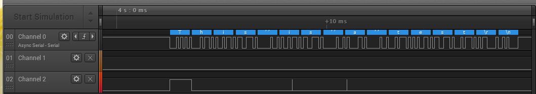
I am having a problem with the transmit complete interrupt on the FR5969 Launchpad. I am sending the data to the UART using DMA and I want the interrupt to disable a RS485 driver when the packet of data is complete. The problem is that the driver gets disabled far too soon. I have reduced the code to about the minimum required to demonstrate my problem. Is this a hardware bug or did I misunderstand something? I am using FreeRTOS so alternatives that require polling flags are not really a desirable option.

#include <msp430.h>
#include <string.h>

char message[] = "This is a test\r\n";

#define LED1_ON  (P4OUT |= 0x40)
#define LED1_OFF (P4OUT &= ~0x40)
#define LED1_TOGGLE (P4OUT ^= 0x40)

#define LED2_ON  (P1OUT |= 1)
#define LED2_OFF (P1OUT &= ~1)
#define LED2_TOGGLE  (P1OUT ^= 1)


int main(void)
{
  WDTCTL = WDTPW + WDTHOLD;
  
  PMMCTL0 = PMMPW;
  PM5CTL0 &= ~LOCKLPM5;           // disable GPIO power on default

  // Configure I/O ports as outputs, low

  P1OUT = P2OUT = P3OUT = P4OUT = PJOUT = 0;
  P1DIR = P2DIR = P3DIR = P4DIR = PJDIR = -1;
  
  FRCTL0 = FWPW|NACCESS_1;        // set 1 FRAM wait state
  FRCTL0_H = 0;                   // lock FRAM control
  
  CSCTL0 = CSKEY;                 // unlock clock system registers
  CSCTL1 = DCORSEL|DCOFSEL_4;     // Set DCO to 16MHz
  CSCTL2 = SELA__LFXTCLK|SELS__DCOCLK|SELM__DCOCLK; // ACLK = XT1, MCLK = DCO
  CSCTL3 = DIVA__1|DIVM__1|DIVS__16; // set clock dividers

  
  // Startup the LFXT

  PJSEL0 |= BIT4|BIT5;              // assign pins to oscillator
  CSCTL4 &= ~LFXTOFF;               // LFXT On
  // Wait for oscillator to start
  do {
    CSCTL5 &= ~LFXTOFFG;          // clear fault flag
    SFRIFG1 &= ~OFIFG;
  } while(SFRIFG1&OFIFG);

  CSCTL0_L = 0;                    // lock clock system registers

  P3OUT  &= ~0x10;          // disable transmitter
  P2SEL1 |=  0x60;          // assign TXD and RXD pins to module
  P2SEL0 &= ~0x60;

  UCA1CTLW0 |= UCSWRST;
  UCA1CTLW0 = UCSWRST|UCSSEL__SMCLK; // SMCLK (nominal 1MHz)
  UCA1BRW = 6;                       // this is always 6 for 9600bps
  UCA1MCTLW = 0x2081;       // default value for now
				       
  UCA1CTLW0 &= ~UCSWRST;    // start UART

  DMACTL0 = DMA0TSEL__UCA1TXIFG;
  DMA0CTL = DMADT_0|DMASRCINCR_3|DMADSTBYTE|DMASRCBYTE;
  DMA0DA_L = (int)&UCA1TXBUF;
  DMA0SA_L = (int)message+1;
  DMA0SZ = strlen(message)-1;                 // count of bytes to transfer

  UCA1IE |= UCTXCPTIE;
  __eint();
  
  while(1)
    {
      __delay_cycles(32000000L);
      LED2_ON;
      P3OUT |= 0x10;            // Enable RS-485 transmitter
      DMA0CTL |= DMAEN;           // enable DMAC
      UCA1TXBUF = message[0];           // transmit first byte of packet
    }

}


__attribute__((wakeup, interrupt(USCI_A1_VECTOR))) void rxISR(void)
{
  switch(UCA1IV)
    {
    case USCI_UART_UCTXCPTIFG:
      P3OUT &= ~0x10;          // disable RS485 transmitter
      LED2_OFF;
      break;
    }
}

  • I do not understand line #61 and #62 of your code. But I do know your intention.

    I think in each iteration of the while-loop, you transmitted a total of 16 bytes (strlen). As a result, UCTXCPTIFG is set 16 times (once after each of those 16 bytes is completed). And is cleared by your ISR 16 times. 15 of them are too early and only the last one is the one you want.
  • Those two lines are the result of my seeing the code normally generated to set those registers. But that is a rant for another time.

    I have been trying out checking UCTXIFG in the ISR before disabling the RS485 transmitter and it seems to be working.

  • You are right.

    TXIFG is also set 16 times. But DMA only clears the first 15 of them by loading TXBUF. The last TXIFG is not cleared!
    There are other ways too. But if this works, that is good enough.

    BTW your line #19 is unnecessary.
  • I have posted an example that may be relevant.
    e2e.ti.com/.../470860
  • That is just another example of this hardware bug. Or maybe it is a documentation bug. slau367g clearly states (Table 21-6) that the transmit complete interrupt is only supposed to happen if the transmit buffer register is empty when the stop bit finishes. It seems to be pretty clear that it generates an interrupt every time a stop bit completes no matter what the status of the transmit buffer register.


    So is it the hardware or the documentation that is wrong?

  • I just try to make my code work the way I expect. It seems to work

    I do not know if the hardware or the documentation is wrong.

    Could help to answer that question?

  • I'll look into this. I'll try to see if I can reproduce/figure out the issue today or tomorrow, otherwise unfortunately it will go into next week because of the Thanksgiving holiday in the US (just fyi).
    -Katie
  • Hi David,

    I tried your code (slightly modified to build in CCS with TI compiler, attached):

    #include <msp430.h>
    #include <string.h>
    
    char message[] = "This is a test\r\n";
    
    #define LED1_ON  (P4OUT |= 0x40)
    #define LED1_OFF (P4OUT &= ~0x40)
    #define LED1_TOGGLE (P4OUT ^= 0x40)
    
    #define LED2_ON  (P1OUT |= 1)
    #define LED2_OFF (P1OUT &= ~1)
    #define LED2_TOGGLE  (P1OUT ^= 1)
    
    int main(void)
    {
      WDTCTL = WDTPW + WDTHOLD;
    
      PMMCTL0 = PMMPW;
      PM5CTL0 &= ~LOCKLPM5;           // disable GPIO power on default
    
      // Configure I/O ports as outputs, low
      P1OUT = P2OUT = P3OUT = P4OUT = PJOUT = 0;
      P1DIR = P2DIR = P3DIR = P4DIR = PJDIR = 0xFFFF;
    
      FRCTL0 = FWPW|NACCESS_1;        // set 1 FRAM wait state
      FRCTL0_H = 0;                   // lock FRAM control
    
      CSCTL0 = CSKEY;                 // unlock clock system registers
      CSCTL1 = DCORSEL|DCOFSEL_4;     // Set DCO to 16MHz
      CSCTL2 = SELA__LFXTCLK|SELS__DCOCLK|SELM__DCOCLK; // ACLK = XT1, MCLK = DCO
      CSCTL3 = DIVA__1|DIVM__1|DIVS__16; // set clock dividers
    
      // Startup the LFXT
      PJSEL0 |= BIT4|BIT5;              // assign pins to oscillator
      CSCTL4 &= ~LFXTOFF;               // LFXT On
    
      // Wait for oscillator to start
      do {
        CSCTL5 &= ~LFXTOFFG;          // clear fault flag
        SFRIFG1 &= ~OFIFG;
      } while(SFRIFG1&OFIFG);
    
      CSCTL0_L = 0;                    // lock clock system registers
    
      P3OUT  &= ~0x10;          // disable transmitter
      P2SEL1 |=  0x60;          // assign TXD and RXD pins to module
      P2SEL0 &= ~0x60;
    
      UCA1CTLW0 |= UCSWRST;
      UCA1CTLW0 = UCSWRST|UCSSEL__SMCLK; // SMCLK (nominal 1MHz)
      UCA1BRW = 6;                       // this is always 6 for 9600bps
      UCA1MCTLW = 0x2081;       // default value for now
      UCA1CTLW0 &= ~UCSWRST;    // start UART
    
      DMACTL0 = DMA0TSEL__UCA1TXIFG;
      DMA0CTL = DMADT_0|DMASRCINCR_3|DMADSTBYTE|DMASRCBYTE;
      __data16_write_addr((unsigned short)&DMA0DA, (unsigned long)&UCA1TXBUF);
      __data16_write_addr((unsigned short)&DMA0SA, (unsigned long)&message+1);
      DMA0SZ = strlen(message)-1;                 // count of bytes to transfer
    
      // Configure DMA channel 0
     // __data16_write_addr((unsigned short) &DMA0SA,(unsigned long) 0x1C20);
                                                // Source block address
      //__data16_write_addr((unsigned short) &DMA0DA,(unsigned long) 0x1C40);
                                                // Destination single address
    
      UCA1IE |= UCTXCPTIE;
      __enable_interrupt();
    
      while(1)
        {
          __delay_cycles(32000000L);
          LED2_ON;
          P3OUT |= 0x10;            // Enable RS-485 transmitter
          DMA0CTL |= DMAEN;           // enable DMAC
          UCA1TXBUF = message[0];           // transmit first byte of packet
        }
    }
    
    //__attribute__((wakeup, interrupt(USCI_A1_VECTOR))) void rxISR(void)
    #pragma vector=USCI_A1_VECTOR
    __interrupt void USCI_A1_ISR(void)
    {
      switch(UCA1IV)
        {
        case USCI_UART_UCTXCPTIFG:
          P3OUT &= ~0x10;          // disable RS485 transmitter
          LED2_OFF;
          break;
        }
    }
    

    This is what I saw on my logic analyzer: (viewer available here: http://downloads.saleae.com/betas/1.2.5/Logic+Setup+1.2.5.exe ) Data from logic analyzer:https://e2e.ti.com/cfs-file/__key/communityserver-discussions-components-files/166/Uart_5F00_test.logicdata

    Screenshot of a portion of it:

    Channel 0 is TXD, Channel 1 is RXD, Channel 2 is P3.0. As you can see, P3.0 is actually cleared right after the first byte, indicating that you entered the ISR for the UCTXCPTIFG right after the first byte. Is that the same thing you were seeing?

    I am currently trying to think through whether this could be because of the way your setup works with the DMA. Here is one idea - the DMA transfer is triggered by UCTXIFG, which will be set when the first data is copied from the TXBUF to the tx shift register to get shifted out on the line. However, if this data finishes being shifted out on the line before the DMA transfer into TXBUF happens, then I think you would see UCTXCPTIFG be set. So I'm wondering if it could be a timing type of issue between the module and the DMA in this case? I think a potential problem is because the DMA is triggering off of one interrupt but you are interrupting off of a different one, and these have different timings.

    What are you trying to use UCTXCPTIFG for in this case? If you are simply trying to detect the end of your transmission actually having gone out on the line, then I would probably enable the DMA interrupt, which should fire only after your entire string transmits, and then in the DMA ISR enable the UCTXCPTIFG interrupt to check if that very last byte was all the way shifted out. I think such a solution where you are only checking if the very last byte of the packet gets shifted out (when you know you aren't waiting for another DMA transfer) would be a better more robust option if this is your goal, since the timings are going to be more known/visible/controllable in that case.

    Regards,

    Katie

  • I don't have a DSO so what I am going on is that the RS485 transmitter was disabled before the full packet of data was sent. I monitored the RS485 line and only received one byte.

    As for DMA, my example was from the version of my code after I decided to try out an RTOS. Before that I used a simple polling loop and then waited on UCBUSY to disable the RS485 transmitter. When I changed it to use the transmit complete interrupt, it failed the same way. So it wasn't the fault of the DMAC timing.

    I will keep the DMA interrupt idea in mind. But at first thought I suspect that after the DMA interrupt there will be two more transmit complete interrupts.

  • Katie,

    I wrote an example to demonstrate this without using DMA. My code sends all 17 bytes of a string one after another whenever TXIFG generates an interrupt. After the 17th, it stops sending. I also enabled TXCPTIFG interrupt and counted. I found that 17 TXCPTIFG interrupt were generated. According to the documents, only the very last one should have happened.

    --OCY

    #include <msp430fr6989.h>
    
    const char msg[] = "This is a test.\r\n";
    const char * ptr;
    volatile int bytes_in_queue;
    
    int main(void)
    {
      WDTCTL = WDTPW + WDTHOLD;
      PM5CTL0 &= ~LOCKLPM5;
        
      P3SEL0 |=  0x30;                      // assign UCA1TXD and UCA1RXD pins
    
      P1OUT = 0;
      P1DIR = BIT0;                         // use LED to indicate TXD status
    
      UCA1CTLW0 |= UCSWRST;
      UCA1CTLW0 = UCSWRST|UCSSEL__SMCLK;
      UCA1BRW = 6;
      UCA1MCTLW = 0x2081;
      UCA1CTLW0 &= ~UCSWRST;
    
      __delay_cycles(10000L);
     
      bytes_in_queue = 0;
      ptr = msg;
      UCA1IE = UCTXIE|UCTXCPTIE; 
      
      P1OUT |= BIT0;                        // indicate begin TXD
      __bis_SR_register(CPUOFF|GIE);
      P1OUT &= ~BIT0;                       // indicate TXD complete
    
    // ... ... ... ... ...  
    
      __delay_cycles(10000L);
    }
    
    #pragma vector = USCI_A1_VECTOR
    __interrupt void usci_a1_isr (void)
    {
      switch (__even_in_range(UCA1IV, 8))
      {
      case USCI_NONE:
        break;
      case USCI_UART_UCRXIFG:
        break;
      case USCI_UART_UCTXIFG:
        if (*ptr)
        {
          UCA1TXBUF_L = *ptr++;
          bytes_in_queue++;
        }
        break;
      case USCI_UART_UCSTTIFG:
        break;
      case USCI_UART_UCTXCPTIFG:
        if ((--bytes_in_queue) == 0)
          __bic_SR_register_on_exit(CPUOFF|GIE);
        break;
      }
    }

  • Thanks for providing your test code old_cow_yellow. I'll try to look into it more (this will probably be next week because I'm out-of-office the rest of this week). But I do want to make sure our module is working as expected - to at the least update the user's guide if it's simply unclear, or to file a bug if it does seem to be a hardware problem.
  • Just an update: we are still looking into this one - hasn't been forgotten!
  • OCY, David,

    Interesting bug! I am able to reproduce it. 

    The picture shows TX, The time spent in TXIFG (while pulse is high), and the time spent in TXCPT. I'm not able to observe a case where the TXCPTIFG flag is not asserted.

    I'll get with the systems team and report back.

    Best regards,

    Cameron

  • Good, thanks for looking into this.

    For , a work-around could be like this:

    Add a static counter in the TXCPTIFG ISR, and disable RS485 transmitter only after that counter reaches strlen(message).

  • The timing is such that checking TXIFG works just fine. It appears that it is set one bit time later than TXCPTIFG. At 9600bps, that provides plenty of time for the ISR to do its thing.
  • All,

    It appears that the TXCPTIFG is working correctly after all. This is the response I got back from our systems team: 

    "the behavior is as intended. The USCI module has no knowledge about the number
    of bytes to be transmitted thus it generates the TXCPTIFG after the
    transmission of each byte. In the DMA use case from the E2E forum it is
    required to add the information that the last byte was loaded into the shift
    register to the USCI interrupt service routine e.g. by querying the interrupt
    flag of the respective DMA channel: only if the interrupt flag of the DMA
    channel (indicating that the last byte was loaded into the shift register)
    disable the RS485 transmitter.
     
    The following untested(!) code snippet should illustrate the idea:"
    __attribute__((wakeup, interrupt(USCI_A1_VECTOR))) void rxISR(void)
    {
      switch(UCA1IV)
        {
        case USCI_UART_UCTXCPTIFG:
          if (DMA0CTL&DMAIFG) // Interrupt flag of DMA channel 0 set?
          {   // Only if last byte was transmitted, then:
              P3OUT &= ~0x10;          // disable RS485 transmitter
              LED2_OFF;
          }
          break;
        }
    }


  • This reply contradicts the documentation in slau376 at Table 21-6:

    "Transmit complete interrupt. This flag is set, after the complete UART byte in the internal shift register including STOP bit got shifted out and UCAxTXBUF is empty."

    I can believe that the suggested solution is untested because it will not work. The DMAC will generate its interrupt after the last transfer. When the next transmit complete interrupt occurs, UCAxTXBUF will be full and DMAIFG will be set. The result being that the RS495 transmitter is disabled before the last byte starts shifting out.

    Checking TXIFG works at the low bit rate I am using but could have trouble if interrupt latency (there are other interrupts of course) prevents checking TXIFG before one bit time elapses. At higher bit rates the only solution appears to be counting transmit complete interrupts. Either using the known packet size or counting off the two after DMAIFG.

  • I think what he means is that only after you get the DMA interrupt you would enable the TXCPTIE to get the last transmit complete interrupt only (instead of for each byte).
    We're still working to clarify on the doc discrepancy that you mentioned - I think they misunderstood what we were asking (that the buf being empty not seeming to matter is what doesn't match, not actually anything to do with the number of bytes in particular).
    -Katie
  • Hi David,

    To update you on the latest status: we've now filed the UCTXCPTIFG behavior to be filed as a potential bug. We believe we were able to reproduce it, now a team will be looking further into root cause of what we were seeing. It will likely be in the new year before we have any more update, due to teams being short-staffed over the holidays, so I wanted to let you know. Hopefully you've been able to workaround the behavior for your own use-case in the meantime, and thanks for reporting this.

    Regards,
    Katie
  • Dear, Katie,

    Happy new year!

    How dose this case go? My customer faces the same question to use UCTXCPTIFG to judge the data transmit finish.

    Thanks and best regards,

    Hardy

  • Hardy,
    This case is still being investigated internally. I will update as soone as we have new information.

    Best regards,
    Cameron
  • Update: the investigation is still ongoing. Simulations are needed and may be late Feb before we have another update. Sorry for the delay.
    -Katie
  • Katie,


    I'm wondering. If we get the UCTXCPTIFG and we find ~UCBUSY, is that enough to *know* that the last char has hit the wire? I guess the question boils down to "when is UCBUSY not set?"

    As a followup, if I get UCTXCPTIFG and UCBUSY is set, can I be assured of getting another UCTXCPTIFG when I return from this one? i.e. if UCBUSY, then can we assume there is another byte being sent, and we can count on an additional UCTXCPTIFG? Is this race condition waiting to foul us up?

    I'm beginning to think the only safe method is to wait until one's xmit buffer is exhausted, turn off TXIFG, wait for the next UCTXCPTIFG, then return in ACTIVE mode and have the line below the LPMx spin on UCBUSY being set. Seems a shame to have to finish with a spin wait after going to the trouble of writing a fully interrupt driven UART routine.

  • Hi James,

    Unfortunately as I mentioned in my last post, the investigation involves some simulations to be run and these are ongoing - we aren't likely to have more info until end of this month (Feb) as stated above. I'd like to understand the results from the simulations before making any recommendation, since it was seeming like the behavior was unclear in relation to what I had expected from the user's guide - we don't want to make a suggestion and then find out from our simulations that it won't work later. Sorry for the delay.

    Regards,
    Katie
  • I tried checking UCBUSY and it only worked some of the time while checking TXIFG has seems to work all of the time. At least it does at 9600bps.
  • James' method sounds very reasonable to me. I will try to run my kind of "simulation" tomorrow and report back.
    --OCY
  • Hi Katie. We're now 1 week into March. How are those simulations going?
  • Hi James,
    This bug has been confirmed is being filed as an errata. There should be a work around once the errata is released. If needed I can investigate the workaround ahead of time for you! :-)
  • Well, if it's not too much trouble, yes, I'd like a work around as soon as it's settled.

    Can I ask that you alert me when the errata is released as well?

    thanks

  • Any news on this? Any details that you can share? Any ETA?
  • James,
    Let me get a response from the appropriate people.
  • James,
    This is going to be files as USCI42, which does not have a work around. For the verbiage of this errata, please see: www.ti.com/.../slaz681a.pdf (This errata sheet is for FR5994).
  • Thanks, two questions
    1) This errata will apply to all eUSCI devices, correct?
    2) Did my suggested work-around of waiting for UCTXCPTIFG checking for ~UCBUSY prove to be ineffective in the simulations?
  • I had concerns that UCBUSY could be perturbed by received data, but, that's not a problem for my Modbus/RS485 case.
  • I tried checking UCBUSY and that worked most of the time but it occasionally failed. Checking TXIFG seems to work a lot better.
  • James,

    This is the official errata that will be made public for FR5969 when we have a chance to update that device errata sheet. MSP430FR5969 has been confirmed to exhibit the bug. We have confirmed that this is an issue on a number of devices, and FR5969 is included. The UCTXCPTIFG flag will be triggered at the last stop bit of every UART byte transmission regardless of using DMA or not.

    As for a workaround, we do not have an official one available. However, as OCY said on a previous post, you could enabled a static counter in the TXCPTIFG ISR to count until the point you wish to care about. This is an application dependent solution however.
  • Hi team,

    I see this fault is still open.

    Possible work-around is as follows:

    ( Forth Snippet )   
       DMAIFG     DMAxCTL DMA4-Base + waitflagset          \ wait for DMA to complete
       UCTXIFG    IFG eUSCI-A3-Base + waitflagset          \ wait txbuf
       UCTXCPTIFG IFG eUSCI-A3-Base + bic!                 \ clear stop bit flag   
       UCTXCPTIFG IFG eUSCI-A3-Base + waitflagset          \ wait stop bit flag 
     

    Kind regatds,

    c-:

  • UCTXCPTIFG in specific eUSCIs is broken. There are outstanding errata for this. USCI42.

**Attention** This is a public forum