This thread has been locked.

If you have a related question, please click the "Ask a related question" button in the top right corner. The newly created question will be automatically linked to this question.

MSP430 link error Error[e16]: IAR IDE 7.2

Other Parts Discussed in Thread: SEGGER, MSP430FG4619

I got the following error while "make" command for my code in IAR IDE 7.2... when i looked through the forum in an earlier reply it said to change the "project options" to "assembler only" but there is no "assembler only" option in the project options>>general tab in IAR IDE 7.2

I tried using "Exclude RESET vector" but the error changes and multiple errors crop up

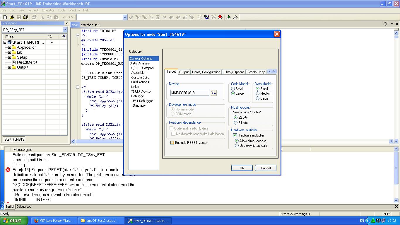
Error[e16]: Segment RESET (size: 0x2 align: 0x1) is too long for segment  
definition. At least 0x2 more bytes needed. The problem occurred while  
processing the segment placement command  
"-Z(CODE)RESET=FFFE-FFFF", where at the moment of placement the  
available memory ranges were "-none-"
   Reserved ranges relevant to this placement:
   ffc0-ffff            INTVEC
Error while running Linker

  • Hi Vikash,

    You mentioned "Exclude RESET vector" - can you provide more information and a screenshot of where this is so we can better understand your issue? What are you trying to do by excluding the reset vector - maybe you could provide a little more information about your need?

    Are you trying to make an Assembly project, is that why you mentioned assembler only setting above?

    Regards,
    Katie
  • Are you using assembly code?
    If so, you can use either of the following two methods to control the placement of the Reset Vector.
    (1) absolute
    ORG 0xFFFE
    DW my_code
    (2) "relative"
    COMMON RESET
    DW my_code
  • Hello Katie,

    I am trying to put tasks (written in assembly code MSP430FG4619) in an RTOS framework (RTOS used is embOS by SEGGER). In the present project i have tried to put two tasks written in assembly code in the "sample 2 task" project (provided with RTOS embOS). The sample 2 task works without my assembly codes put into it and the assembly codes do not show any error when compile/make/build individually.

    Here is a snapshot of "project options" which has EXCLUDE reset vector. I am not sure whether "EXCLUDE reset vector" is the solution to my issue.

    Yes i am working with assembly code. But the API of RTOS (embOS) are in C/C++

  • Dear sir,

    This is my code and i understand the issue is in the final 6 lines. Can you guide me how to implement your solution. (PS: this code is not written by me, i am trying to put this code as a task in RTOS embOS. Individually this code can be make/compile/build, but when used as a task in RTOS it comes up with the error.

    #include  <msp430xG46x.h>

    ;-------------------------------------------------------------------------------

               RSEG    CSTACK                  ; Define stack segment

    ;-------------------------------------------------------------------------------

    /*            RSEG    CODE                    ; Assemble to Flash memory*/

    ;-------------------------------------------------------------------------------

    /*         RSEG    INFO                  ; Assemble to INFORMATION MEMORY

    */

    ;-----------------------------------------------------------------------------

              ; ORG     02100

    RESET       mov.w    #SFE(CSTACK),SP    ;#02100h,SP;       ; Initialize stackpointer

              ; bis.b   #GIE,SR             ;enabling general interrupts

    /*StopWDT     mov.w   #WDTPW+WDTHOLD+WDTNMI+WDTTMSEL+WDTSSEL,&WDTCTL  ; Stop WDT

    */

    ;-----------------------------------------------------------------

    START      

               MOV.W   #TX_DATA0,R15          ;Address Of Tx_Data0 In R15

               MOV.W   #TX_DATA1,R14

               MOV.W   #TX_DATA2,R13

               MOV.W   #TX_DATA3,R12

               MOV.B   #02,R11

               MOV.B   #08,R10

               MOV.B   #02,R9

               MOV.B   #02,R8

    SETUPSVS    MOV.B   #018H,&SVSCTL            ;threshold voltage Vth = 1.9V

    SETUPRTC    MOV.B   #30h,&RTCCTL       ; real time clock in calendar mode

                Bis.B   #RTCBCD,&RTCCTL

    SETUPP3    ; BIS.B   #UCSWRST,&UCB0CTL1 ;keeping the USCIB0 in reset

              Bis.B   #06h,&P3SEL             ; Assign I2C pins to USCI_B0

    I2c         BIS.B   #UCSWRST,&UCB0CTL1      ;holding the usci port high

               MOV.B   #0Fh,&UCB0CTL0          ;synch,I2C,master mode

               BIS.B   #UCSSEL_2+UCSWRST,&UCB0CTL1

                                               ; Use SMCLK, keep SW reset

               MOV.B   #11,&UCB0BR0            ; fSCL = SMCLK/11 = 95.3kHz

               MOV.B   #00,&UCB0BR1

    IOEXPANDER  

              BIS.B   #UCB0TXIE,&IE2          ; Enable TX interrupt

               BIC.B   #UCSWRST,&UCB0CTL1 ; Clear SW reset, resume operation            

               MOV.W   #040h,&UCB0I2CSA        ; Set slave address of IO Expander

    TX       BIS.B   #UCTXSTT+UCTR,&UCB0CTL1 ;generate start condition in tx mode

    Wait10     mov.w   #32,R6               ; load R15 with value for delay

    L11         dec.w   R6                     ; decrement R15

              jnz     L11                     ; if R15 is not zero jump to L1

               EINT   ; ; enable global interrupt

               nop

               nop

               nop

               BIT.B   #UCB0TXIFG,&IFG2           ; check if transmit interrupt flag is set

               JNZ     USCIAB0TX_ISR0           ;if set go to USCIAB0TX_ISR0          

    ;...............................................................................  

    TX_DATA0

               DB 04h ; address of shutdown register in max7300

               DB 01H           ;switch on max 7300

    TX_DATA1          

               DB 09H ;port configuration registers from 09h to 0fh

               DB 055H ; configuring in output in subsequent write mode

               DB 055H

               DB 055H

               DB 055H

               DB 055H

               DB 055H

               DB 055H

    TX_DATA2

               DB 044h ;configuring ports for DSP1 and DSP3

               DB 0aeH

    TX_DATA3

               DB 030h ;port for pwrenjtag

               DB 01H

    ;...............................................................................            

    USCIAB0TX_ISR0            

               MOV.B   @R15+,&UCB0TXBUF  ; moving the data in TX_DATA0 to Tx buffer

    Wait        mov.w   #8,R7               ; load R15 with value for delay

    L1          dec.w   R7                     ; decrement R15

               jnz     L1                      ; if R15 is not zero jump to L1

               DEC     R11  ;for two data bytes

               JNZ     USCIAB0TX_ISR0

               BIC.B #UCB0TXIFG,&IFG2 ;transmit interrupt flag is cleared

    Wait3      mov.w   #32,R4               ; load R15 with value for delay

    L4         dec.w   R4                     ; decrement R15

              jnz     L4                      ; if R15 is not zero jump to L1

              BIS.B #UCTXSTP,&UCB0CTL1 ;I2C stop condition

    Wait1      mov.w   #32,R6               ; load R15 with value for delay

    L2         dec.w   R6                     ; decrement R15

              jnz     L2                      ; if R15 is not zero jump to L1          

              BIC.B  #UCTXSTP,&UCB0CTL1 ;moving out of stop condition

              BIS.B   #UCTXSTT+UCTR,&UCB0CTL1 ;generate start condition in tx mode          

    USCIAB0TX_ISR1

              MOV.B   @R14+,&UCB0TXBUF ;transmitting the eight data bytes of TX_DATA1

    Wait2      mov.w   #32,R5               ; load R15 with value for delay

    L3         dec.w   R5                     ; decrement R15

              jnz     L3                      ; if R15 is not zero jump to L1          

              DEC     R10

              JNZ     USCIAB0TX_ISR1

              BIC.B #UCB0TXIFG,&IFG2

    Wait7      mov.w   #32,R6               ; load R15 with value for delay

    L8         dec.w   R6                     ; decrement R15

              jnz     L8                     ; if R15 is not zero jump to L1

              BIS.B #UCTXSTP,&UCB0CTL1

    Wait6      mov.w   #32,R6               ; load R15 with value for delay

    L7         dec.w   R6                     ; decrement R15

              jnz     L7                      ; if R15 is not zero jump to L1

             BIC.B  #UCTXSTP,&UCB0CTL1

              BIS.B  #UCTXSTT+UCTR,&UCB0CTL1 ;generate start condition in Tx mode

    Wait9      mov.w   #32,R6               ; load R15 with value for delay

    L10         dec.w   R6                     ; decrement R15

              jnz     L10                      ; if R15 is not zero jump to L1

              EINT   ;

              BIT.B   #UCB0TXIFG,&IFG2           ;

              JNZ     USCIAB0TX_ISR2    

    USCIAB0TX_ISR2

              MOV.B   @R13+,&UCB0TXBUF ;transmitting data at TX_DATA2

    Wait8      mov.w   #8,R6               ; load R15 with value for delay

    L9         dec.w   R6                     ; decrement R15

              jnz     L9                      ; if R15 is not zero jump to L1          

              DEC     R9

              JNZ     USCIAB0TX_ISR2

              BIC.B #UCB0TXIFG,&IFG2

    Wait4      mov.w   #32,R6               ; load R15 with value for delay

    L5         dec.w   R6                     ; decrement R15

              jnz     L5                      ; if R15 is not zero jump to L1

              BIS.B #UCTXSTP,&UCB0CTL1

    Wait5      mov.w   #32,R6               ; load R15 with value for delay

    L6         dec.w   R6                     ; decrement R15

              jnz     L6                      ; if R15 is not zero jump to L1

              BIC.B  #UCTXSTP,&UCB0CTL1

              BIS.B  #UCTXSTT+UCTR,&UCB0CTL1 ;generate start condition in Tx mode

    Wait15     mov.w   #32,R6               ; load R15 with value for delay

    L16        dec.w   R6                     ; decrement R15

              jnz     L16                     ; if R15 is not zero jump to L1

              EINT   ;

              bit.b   #UCB0TXIFG,&IFG2           ;

              JNZ     USCIAB0TX_ISR3    

    USCIAB0TX_ISR3

              MOV.B   @R12+,&UCB0TXBUF ;transmitting data at TX_DATA3

    Wait13     mov.w   #8,R6               ; load R15 with value for delay

    L14        dec.w   R6                     ; decrement R15

              jnz     L14                     ; if R15 is not zero jump to L1

              DEC     R8

              JNZ     USCIAB0TX_ISR3

              BIC.B #UCB0TXIFG,&IFG2

    Wait14     mov.w   #64,R6               ; load R15 with value for delay

    L15       dec.w   R6                     ; decrement R15

              jnz     L15                     ; if R15 is not zero jump to L1

              BIS.B #UCTXSTP,&UCB0CTL1

    Wait11     mov.w   #64,R6               ; load R15 with value for delay

    L12        dec.w   R6                     ; decrement R15

              jnz     L12                     ; if R15 is not zero jump to L1

    EXIT_TX

               BIC.B #UCB0TXIFG,&IFG2

               BIS.B #UCTXSTP,&UCB0CTL1

    Wait12     mov.w   #32,R6               ; load R15 with value for delay

    L13        dec.w   R6                     ; decrement R15

              jnz     L13                     ; if R15 is not zero jump to L1

              RETI

    ;------------------------------------------------------------------------------

               COMMON  INTVEC                  ; Interrupt Vectors

    ;------------------------------------------------------------------------------

               ORG     USCIAB0TX_VECTOR        ; USCI_B0 I2C Data Int Vector

               DW      USCIAB0TX_ISR0

               ORG     RESET_VECTOR            ; MSP430 RESET Vector

               DW      RESET                   ;

              END

  • Under normal circumstances, the code you presented does not make any sense. I think it is written by someone for the sole propose of experimenting how to load data into UCB0TXDBUF. He/she probably already have existing code already loaded into the Flash memory of hes/her chip. The current code is intended to be loaded into the high address end of RAM while retaining the contents of Flash of his/her existing code. If you do not have the same situation, needs and goals, this code is of no use to you.
  • Hi Vikash,

    I think in this case it might be best to reach out to SEGGER for help with embOS because it's a third party software that I don't really know anything about unfortunately. They should be experts about the best way to incorporate things into tasks in their own RTOS though.

    -Katie
  • Dear Sir,
    I think that is what the code is expected to do. I just need to figure out how to solve the error. In a similar assembly code ( without putting it in RTOS) the same error was debugged by changing project settings to "assembly only" mode (IAR IDE ver 4.11B). However, in IAR IDE ver 7.2 there is no provision of "assembly only" mode. (And i cant use RTOS in ver4.11B because the compiler doesn't support RTOS). Any solutions ?
  • The original code (without your modifications) can be assembled, linked, and downloaded. And it can be used the way it is designed to be used. What you added near the end does not have any effect except generating error messages and stop it from being linked and downloaded.

**Attention** This is a public forum