Because of the holidays, TI E2E™ design support forum responses will be delayed from Dec. 25 through Jan. 2. Thank you for your patience.

This thread has been locked.

If you have a related question, please click the "Ask a related question" button in the top right corner. The newly created question will be automatically linked to this question.

MSP430I2040 Not Working

Other Parts Discussed in Thread: MSP430I2040, EVM430-I2040S

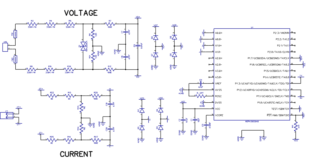
       I have started working with MSP430I2040 recently. I tried to measure from 0vdc to 20vdc signal from a DC source, but the values i got are very random.  I measured voltage at the ADC pins with  multi-meter and it is dividing exactly as we calculated, but i am not able to find out where the problem is. Below is the circuit, Please let me know if there is anything wrong with the circuit.

Regards,

Varaprasad.

  • Hi Varaprasad,

    If you've measured the voltage at the ADC pins with a multi-meter and they are as you expected then we should be looking at your ADC code instead of the circuitry. Can you provide this code as well as what voltages are being input to the MSP430 and what ADC results you get as compared to what you expect?

    Regards,
    Ryan
  • Hi Ryan,

           Thanks for the reply. Below attached are the code and the ADC results. The main purpose of our circuit is to allow user to connect the input in both the directions, which makes the ground as floating.This is done to achieve reverse polarity protection and isolation from the Micro-controller ground. Please let me know if this floating ground is affecting the ADC output. On the firmware side we tried both binary and 2's complement mode. Both are giving random values. 

    The code is taken from TI example library and modified:

    /* --COPYRIGHT--,BSD
     * Copyright (c) 2014, Texas Instruments Incorporated
     * All rights reserved.
     *
     * Redistribution and use in source and binary forms, with or without
     * modification, are permitted provided that the following conditions
     * are met:
     *
     * *  Redistributions of source code must retain the above copyright
     *    notice, this list of conditions and the following disclaimer.
     *
     * *  Redistributions in binary form must reproduce the above copyright
     *    notice, this list of conditions and the following disclaimer in the
     *    documentation and/or other materials provided with the distribution.
     *
     * *  Neither the name of Texas Instruments Incorporated nor the names of
     *    its contributors may be used to endorse or promote products derived
     *    from this software without specific prior written permission.
     *
     * THIS SOFTWARE IS PROVIDED BY THE COPYRIGHT HOLDERS AND CONTRIBUTORS "AS IS"
     * AND ANY EXPRESS OR IMPLIED WARRANTIES, INCLUDING, BUT NOT LIMITED TO,
     * THE IMPLIED WARRANTIES OF MERCHANTABILITY AND FITNESS FOR A PARTICULAR
     * PURPOSE ARE DISCLAIMED. IN NO EVENT SHALL THE COPYRIGHT OWNER OR
     * CONTRIBUTORS BE LIABLE FOR ANY DIRECT, INDIRECT, INCIDENTAL, SPECIAL,
     * EXEMPLARY, OR CONSEQUENTIAL DAMAGES (INCLUDING, BUT NOT LIMITED TO,
     * PROCUREMENT OF SUBSTITUTE GOODS OR SERVICES; LOSS OF USE, DATA, OR PROFITS;
     * OR BUSINESS INTERRUPTION) HOWEVER CAUSED AND ON ANY THEORY OF LIABILITY,
     * WHETHER IN CONTRACT, STRICT LIABILITY, OR TORT (INCLUDING NEGLIGENCE OR
     * OTHERWISE) ARISING IN ANY WAY OUT OF THE USE OF THIS SOFTWARE,
     * EVEN IF ADVISED OF THE POSSIBILITY OF SUCH DAMAGE.
     * --/COPYRIGHT--*/
    /*******************************************************************************
     * MSP430i2xx EUSCI_A UART - Loopback at 115200 Baud
     *
     * Description: In this example, the UART RX and TX pins are connected to
     * create a loopback of communication data. The example shows how to properly
     * initialize UART communication at baud rate of 115200 using SMCLK as the
     * source. After the byte is put into the buffer to send the device goes into
     * LPM until it has received the sent byte. If data corruption occurs then
     * the LED will be turned on indicating a problem.
     *
     *
     * Author: Zack Lalanne
     ******************************************************************************/
    
    #include "driverlib.h"
    
    volatile uint32_t value32 = 0;
    
    int main(void) {
        // Configuration for 9600 UART with SMCLK at 16384000
        // These values were generated using the online tool available at:
        // software-dl.ti.com/.../index.html
        EUSCI_A_UART_initParam uartConfig = {
            EUSCI_A_UART_CLOCKSOURCE_SMCLK,          // SMCLK Clock Source
            106,                                       // BRDIV = 8
            10,                                      // UCxBRF = 14
            206,                                      // UCxBRS = 34
            EUSCI_A_UART_NO_PARITY,                  // No Parity
            EUSCI_A_UART_MSB_FIRST,                  // MSB First
            EUSCI_A_UART_ONE_STOP_BIT,               // One stop bit
            EUSCI_A_UART_MODE,                       // UART mode
            EUSCI_A_UART_OVERSAMPLING_BAUDRATE_GENERATION  // Oversampling Baudrate
        };
    
        WDT_hold(WDT_BASE);
    
        // Setting the DCO to use the internal resistor. DCO will be at 16.384MHz
        CS_setupDCO(CS_INTERNAL_RESISTOR);
    
        // SMCLK should be same speed as DCO. SMCLK = 16.384MHz
        CS_clockSignalInit(CS_SMCLK, CS_CLOCK_DIVIDER_1);
    
        // Settings P1.2 and P1.3 as UART pins. P1.4 as LED output
        GPIO_setAsPeripheralModuleFunctionInputPin(GPIO_PORT_P1,
                                                   GPIO_PIN2 | GPIO_PIN3,
                                                   GPIO_PRIMARY_MODULE_FUNCTION);
    
        // Configure and enable the UART peripheral
        EUSCI_A_UART_init(EUSCI_A0_BASE, &uartConfig);
        EUSCI_A_UART_enable(EUSCI_A0_BASE);
    
        EUSCI_A_UART_enableInterrupt(EUSCI_A0_BASE,
                                     EUSCI_A_UART_RECEIVE_INTERRUPT);
    
        // Internal ref
       SD24_init(SD24_BASE, SD24_REF_INTERNAL);
    
       //Ch0 single mode
       SD24_initConverterAdvancedParam param = { 0 };
       param.converter = SD24_CONVERTER_0;
       param.conversionMode = SD24_SINGLE_MODE;
       param.groupEnable = SD24_NOT_GROUPED;
       param.inputChannel = SD24_INPUT_CH_ANALOG;
       param.dataFormat = SD24_DATA_FORMAT_BINARY;
       param.interruptDelay = SD24_FOURTH_SAMPLE_INTERRUPT;
       param.oversampleRatio = SD24_OVERSAMPLE_256;
       param.gain = SD24_GAIN_1;
       SD24_initConverterAdvanced(SD24_BASE, &param);
       SD24_enableInterrupt(SD24_BASE, SD24_CONVERTER_0, SD24_CONVERTER_INTERRUPT);
    
      // Delay ~200us for 1.2V ref to settle
      __delay_cycles(3200);
    
    
        while(1)
        {
    			__no_operation();               // SET BREAKPOINT HERE
    
    			// Go to sleep and wait for user input
    			__bis_SR_register(LPM0_bits | GIE);
    
    			SD24_startConverterConversion(SD24_BASE, SD24_CONVERTER_0);
    
    			// Go to sleep and wait for ADC conversion
    			__bis_SR_register(LPM0_bits | GIE);
    
    			EUSCI_A_UART_transmitData(EUSCI_A0_BASE, (value32 >> 8));
    			EUSCI_A_UART_transmitData(EUSCI_A0_BASE, value32);
    
    
    			__no_operation();
        }
    }
    
    #pragma vector=USCI_A0_VECTOR
    __interrupt void USCI_A0_ISR(void)
    {
            switch (__even_in_range(UCA0IV, USCI_UART_UCTXCPTIFG)) {
            case USCI_NONE: break;
            case USCI_UART_UCRXIFG:
    
                    EUSCI_A_UART_receiveData(EUSCI_A0_BASE);
                    // Leave LPM so next byte can be sent
                    __bic_SR_register_on_exit(LPM0_bits);
    
                    break;
            case USCI_UART_UCTXIFG: break;
            case USCI_UART_UCSTTIFG: break;
            case USCI_UART_UCTXCPTIFG: break;
            default: break;
            }
    }
    
    
    #pragma vector=SD24_VECTOR
    __interrupt void SD24_ISR(void)
    {
            switch (__even_in_range(SD24IV, SD24IV_SD24MEM3))
            {
            case SD24IV_NONE: break;
            case SD24IV_SD24OVIFG: break;
            case SD24IV_SD24MEM0:
    
            		value32 = SD24_getHighWordResults(SD24_BASE, SD24_CONVERTER_0);
    
                   break;
            case SD24IV_SD24MEM1: break;
            case SD24IV_SD24MEM2: break;
            case SD24IV_SD24MEM3: break;
            default: break;
            }
            __bic_SR_register_on_exit(LPM0_bits);   // Wake up from LPM0
    }
    
    
      EXPECTED VALUES ACTUAL VALUES  
    Vin(V) Calculated Vout (mV) Measured Vout (mV) E-HEX E-DEC A-HEX A-DEC Vout (mV) Vdiff (mV)
                     
    10 15.129 15.000 844E 33870 645D 25693 -97.160 112.289
    9 13.616 13.500 83E0 33760 87A7 34727 26.903 -13.287
    8 12.103 12.000 8372 33650 9D2C 40236 102.557 -90.454
    7 10.590 10.500 8304 33540 B126 45350 172.787 -162.197
    6 9.077 9.000 8295 33429 262E 9774 -315.775 324.852
    5 7.564 7.500 8227 33319 82C9 33481 9.792 -2.227
    4 6.051 6.000 81B9 33209 F032 61490 394.437 -388.385
    3 4.539 4.500 814B 33099 A7A0 42912 139.307 -134.768
    2 3.026 3.000 80DD 32989 FDC6 64966 442.172 -439.147
    1 1.513 1.500 806F 32879 A9CC 43468 146.942 -145.429
    0 0.000 0.000 8000 32768 2EEE 12014 -285.013 285.013
    -1 -1.513 -1.500 7F92 32658 C245 49733 232.979 -234.492
    -2 -3.026 -3.000 7F24 32548 9816 38934 84.677 -87.703
    -3 -4.539 -4.500 7EB6 32438 371C 14108 -256.256 251.718
    -4 -6.051 -6.000 7E48 32328 837C 33660 12.250 -18.301
    -5 -7.564 -7.500 7DDA 32218 E96D 59757 370.638 -378.202
    -6 -9.077 -9.000 7D6C 32108 36C9 14025 -257.396 248.319
    -7 -10.590 -10.500 7CFD 31997 FC63 64611 437.297 -447.887
    -8 -12.103 -12.000 7C8F 31887 68D0 26832 -81.519 69.416
    -9 -13.616 -13.500 7C21 31777 B7AA 47018 195.694 -209.310
    -10 -15.129 -15.000 7BB3 31667 3361 13153 -269.371 254.242

    Regards,

    Varaprasad.

  • Hi Varaprasad,

    I see that you have properly sampled some driverlib examples for your application and as such your code seems to be in working condition. Does Vin accurately represent your differential input voltage (VID)? If so then the full-scale range (FSR) of your input voltage is much too expansive to be handled by the SD24 peripheral. VFSR(+/-) = (+/-)VREF/GAIN. In your case VREF is 1.16 V (typical internal reference value) and your GAIN is 1, the expected VFSR is +/- 1.2 V and the analog input range should not exceed ~80% of that value, or VID = +/- 928 mV in your case. This is all explained in Section 5.6.7 of the MSP430I2040 datasheet.  Please refer to EVMs like the EVM430-I2040S for a better understanding of how the SD24 is intended to operate.

    Regards,
    Ryan

  • Hi Ryan,
    Thanks for the inputs. The voltage range which we designed is well with in the limits(+/- 928mV) as you can see the voltage divider in the circuit (1V = 1.5mV). What we suspect is, this problem might be because of floating ground. Please suggest if the designed circuit can be used or not.

    Regards,
    Varaprasad.
  • Hi Ryan,

                 The ADC is working. It is our mistake that we interpreted UART in wrong way. The LSB should be sent first in the UART but we transmitted MSB everytime. 

    Now it works fine only some tuning is required to get exact values. Thanks for everything.

    Regards,

    Varaprasad.

  • I'm having the same issue with my board where do I patch it to fix this issue?

**Attention** This is a public forum