This thread has been locked.

If you have a related question, please click the "Ask a related question" button in the top right corner. The newly created question will be automatically linked to this question.

MSP432 overheating, or is this normal?

Other Parts Discussed in Thread: CC3100, TPS735, TM4C1294NCPDT

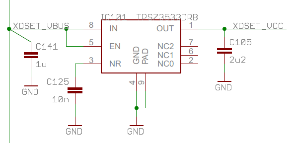
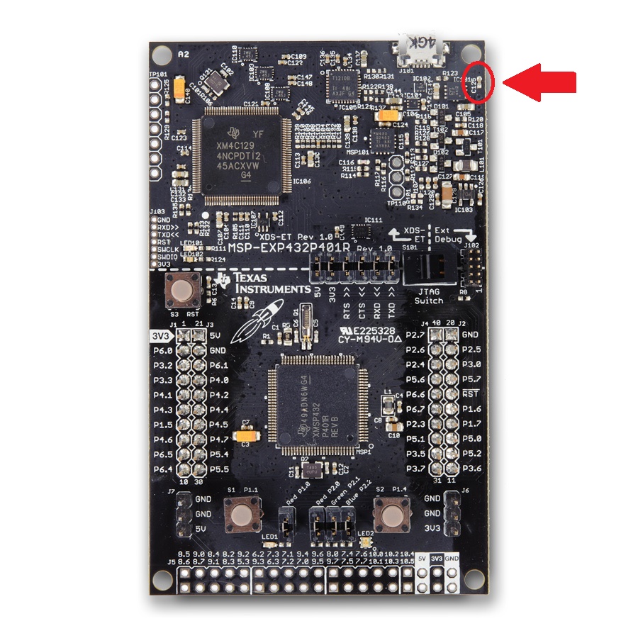
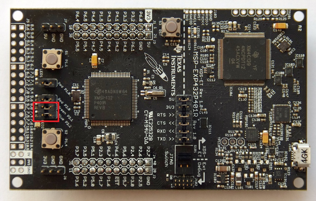
hi, the IC close to the usb connector gets really hot during operation -- see image below. it's hot enough to burn my finger a bit. is this normal? i'm using the MSP432 with the CC3100 booster. thanks, mahesh

  • It is normal if you touched the C125 capacitor. We discussed this problem through some last days many times on this community. So, you shouldn't touch the C125 capacitor, then it didn't happen.
  • Hi Alexey!

    First I will link in some information about the capacitor C125, so that not everyone has to search for it. C125 is connected to IC101 on the MSP-EXP432P401R LaunchPad. It is the 3.3V version of the TPS735 voltage regulator - datasheet here. C125 is a 10nF capacitor connected to the NR pin of the IC. Connecting a capacitor here helps to bypass noise generated by the internal bandgap reference.

    Alexey Bagaev said:
    It is normal if you touched the C125 capacitor.

    How do you know the NR-pin is the problem? Do you think it is more sensitive to electrostatic discharge?

    ESD is a problem for all devices on the board, so everyone using electronics with direct access to the ICs without any protection should be aware of this problem. So keep in mind to always wear an ESD wrist strap when handling electrostatic sensitive devices.

    Or at least discharge yourself before touching the electronics by getting in contact to a blank metal part of a radiator or something else that is earthed.

    Dennis

  • Hi Dennis,

    The problem with TPS735 and 10nF capacitor connected to it as RC-filter is not with ESD.
    1. This board is equipped with 15 kV ESD protection for USB connection.
    2. The ESD is the case for people wearing sintetic clothes.
    3. C125 works as a part of noise filtering for linear pulse generator to provide less noisy power supply for sensitive 14-bit analog-to-digital converter.
    4. Changing the capacitance of noise filter by touching it by hands causes TPS735 voltage ouput rising above operating limits 3.6 V. And it has nothing with ESD.

    Alexey
  • Hi Alexey!

    Thanks for answering. You know this for sure or is it your assumption?

    Dennis
  • Dennis, Practically proven by me.
  • So you think it is not the TPS735 that gets destroyed. Instead a voltage >3.6V will destroy the MSP432P401R or other circuitry? At least for the MSP432P401R one could easily prove that if you would remove the jumper for the 3.3V supply and look if the excessive current consumption stops.

    Edit: The absolute maximum voltage for the MSP432P401R is 4.17V by the way.

  • Hi Alexey!

    Alexey Bagaev said:
    4. Changing the capacitance of noise filter by touching it by hands causes TPS735 voltage ouput rising above operating limits 3.6 V. And it has nothing with ESD.

    Let's have a look at the internal structure of the TPS735 - you will see the following:

    No let's say the device will start up. The 1.208V bandgap reference is directly connected to the negative input of the differential amplifier via the quickstart switch. That means you have a rising voltage at the pin. Now look here:

    A rising voltage on the negative input of the amplifier would bring it's output low which means the P-FET opens and the voltage at the output and the positive pin of the OPAMP goes high until it equals the voltage at the negative input. If both are the same (1.208V in this case), the OPAMP will control the current through the P-FET according to the consumption on the output so the voltage at the resistor divider will always be the same like the one coming from the bandgap reference.

    Now let's look at the opposite situation:

    A negative pulse, now shown at the NR pin because this is what happens when you apply an additional (uncharged) capacity at the pin, will cause the output of the amplifier to go high resulting in a more closing P-FET which results in a lower output voltage. And of course a lower voltage at the positive input of the OPAMP. But the output voltage should decrease when connecting additional capacity while the device is operating. Keep in mind that the quickstart switch is open now and it takes a while to load the extra capacity to the value of the bandgap reference.

    A situation I could imagine - at least in theory - is the following:

    Since the quickstart switch is open while operating, the negative input of the amplifier is somehow "isolated" from the bandgap reference by the 500k resistor. If you now apply a voltage higher than the bandgap reference's one at the NR pin, the error amplifier only sees this voltage and opens the FET until the voltage at the resistor divider on it's positive input equals the voltage at it's negative one (if not limited by the input) which could cause the output voltage to rise over it's desired value. Now it's up to the overshoot detection if it can bring down this higher voltage but it only adds a 400R load to sink some current. If this is not enough, the overvoltage situation might occur. But as I said: Theory. You don't know the exact inner structure of the chip - this is only a functional block diagram. But as a conclusion, I would not say that the electrical connection on NR / C125 couldn't be a critical one - maybe it is, but not because of extra capacity, I think.

    Dennis

  • are you saying that the capacitor is the one radiating the heat? i held the board to remove the USB cable and noticed that the area around it was quite warm. feeling around, i homed in on the IC as the part that was really hot. i'll check again.
  • No, not the capacitor. If something gets warm in that area it will be the voltage regulator. But I did not have any broken board myself yet - and I have a few of those LaunchPads.

  • Hi Alexey!

    I made a small test setup to see if my assumptions are correct - here it is (don't care about the other parts on the rest of the breadboard):

    Sure this is not the most professional test, but better than nothing...

    As you can see I soldered three thin wires to the MSP-EXP432P401R LaunchPad. These are:

    • GND
    • Vout
    • NR (C125)

    Then I took four different capacitors:

    • 100pF
    • 2.2nF
    • 10nF
    • 100nF

    GND of the LaunchPad is connected to one side of each capacitor, the other side of each one is not connected. The longer black wire that has the green arrow on it's left side is connected to NR on it's other end. The end with the arrow will be connected to one of the capacitors while the board is already running. I marked the four pin holes which are the open side of the capacitors with a green circle - I will connect the black wire with the end where the arrow is to those positions.

    Before I make a connection I short the capacitors. Vout goes to the DMM and the oscilloscope that is set to single shot triggered by a rising edge of Vout.

    When connecting the 100pF capacitor, there is no change in the output voltage, so no oscilloscope picture here. But you will see a voltage drop when the 2.2nF capacitor suddenly comes in parallel to C125:

    When connecting the 10nF capacitor, the voltage drop is even larger, and as expected, longer:

    And with 100nF suddenly added in parallel, it looks like this:

    Note that the vertical and the horizontal setting is the same for all three pictures. With the last one, the green LED on the LaunchPad switched off for a short time, means the voltage drop is so long that the TM4C1294NCPDT passes out for a small duration.

    So adding (uncharged) capacitance in parallel to C125 does not cause an overshoot of the output voltage - the regulator behaves exactly as assumed in my earlier post here:

    Dennis

  • Dennis, higher capacitance means also higher impendence. Try to test impendence of the finger skin (should be ~ 2 MΩ) and then try to find according capacitor with relatively equal internal impendence/resistance, if you wish. Any risks of damaging internal circuits the TPS735 you carry. So, try it only if you wish.

  • So, maybe one of you might call me stupid now, but the next test was to destroy the board.

    But since I have some reserves, I will do it...this problem needs to be investigated, I think.

    What I have done now:

    I used the 100n capacitor and charged it before connecting it in parallel to C125. I incremented the voltage in steps of 0.5V, starting at 0.5V - here charged to 0.5V:

    Of course there is still a voltage drop on the output because the applied voltage is lower than the bandgap reference voltage. Same for 1V, but smaller beacuse we are getting closer to the bandgap voltage:

    Now with 1.5V, the output voltage should jump up because it is higher than the bandgap's 1.208V - and that is exactly what happens:

    2V:

    2.5V:

    3V:

    3.5V:

    4V:

    4.5V:

    5V:

    As you can see from 4V up to 5V, the output voltage jumps to the same value each time - but it is simply limited by the input voltage of 5V, so it would jump higher if possible.

    When connecting the parallel capacitance you can see the green LED blink brighter for a short time. At 4V charge, it remains on, at 4.5V it switches off and since it is controlled by the TM4C1294NCPDT, something with the controller seems to happen. The interesting thing: It comes back on after some time, but I could not figure out if it needs some power cycles or just time. Is there a polyfuse somewhere on the board? I will have to look at the schematic.

    One important side info: I do not have the jumpers for the supply of the MSP432P401R connected during all these tests, so since the green LED comes back after some time, it might be the MSP432P401R that will be destroyed by the pulse which did not happen on my board so far and therefore the excessive current consumption did not happen yet which would cause the regulator to get hot. I will test that. The output voltage is about 4.6V - this is too much for the MSP432P401R, for example. I also have to look what the datasheet of the TM4C1294NCPDT says about the absolute maximum ratings.

    Result:

    Again, as expected, a positive voltage pulse (with respect to the internal bandgap voltage) at the NR pin causes the output to rise and this could lead to damage of the following parts.

    That means: The connection at C125 is critical! Bad thing it is at the edge of the board where you might get in contact with it much easier.

    If you are charged and touch it you can damaged the board, even if not charged up to ESD critical levels. ESD, of course, can damage the board, regardless of the C125 connection. But in this case, 4V will bring the output voltage to 4.6V, only limited by the input - this is over the absolute maximum rating for the MSP432P401R.

    Of course 100nF is quite large, so quite much energy stored in it. I don't know the output impedance of the internal bandgap circuit, but even if it was possible to sink the energy of the capacitor, the 500k resistor is the problem because it isolates the NR pin from the bandgap. The NR pin gives you direct access to the negative input of the error amplifier.

    After ten minutes and a few power cycles, my MSP-EXP432P401R still does not light up again...let's see. The voltage regulator is warm, but I touched hotter ICs in the past. The output voltage is still 3.3V, so the regulator seems to be OK - at least not completely down. I have to measure the current. Time to roast the MSP?

    Dennis

  • It is awake again! I connected the NR pin to a discharged capacitor and the green LED lit up. That is interesting now...

    While then trying to get the LED off, it took a few approaches with 5V @ 100nF until this happened. I could get it on again with the first try connecting a discharged 100nF capacitor. A few more tests showed: The number of approaches to get it switching off varies, but it can be woken up by a single low pulse on the output of the regulator by connecting the discharged capacitor to the NR pin.

    Interesting is the fact, that a power cycle does not have the same effect. The LED stays off, even if you short C125 before applying power.

  • It is the time to show the love to the TI products:

    1. Isolate C125 capacitor on remaining boards with small drop of silicon glue.

    2. Study advanced technologies provided by TI.

    Alex

  • I would not say that this is a problem by TI. I now touched the NR pin over and over again, but as long as I have my ESD wrist strap on, everything is fine. You only slightly see the 50Hz mains introduced into the output of the regulator. And bare electronics are not meant to be touched. But of course most people just handle the board without being earthed and in combination with this sensitive pin and the bad result it can lead to, this is a very bad coincidence.

  • I hooked up a DMM in series with the USB power line - this LaunchPad now draws 274mA - I guess this is not normal, so it will be damaged already. I connected the jumpers of the MSP432P401R supply rails and gave it some overvoltage shots, but the current does not increase significantly - only 1 or 2mA when connecting the rails, so normal additional current for the MSP. But something on the emulator side now draws that much current. And at the moment, the green LED doesn't stay off after causing the overvoltage situation. It only switches off very short and then lights up again.

  • The TI company portfolio is based on 65 years of research and appliance. Most pioneers in advanced technologies is too old to be hired or even dead by now. The new generation of employees do not lead to be the same experienced as the old one, but have wider opportunities.

  • Dear & dear (hopefully you are Mike Stein?), Dung asked me to link you in to this thread.

    Dennis
  • Dennis,

    Thanks for looping me in. Great timing as I just sent a similar summary to the team on Friday. We have a future revision coming up that moves C125 inside the board so it is not likely to be touched. But now I am evaluating completely removing C125, as I do not believe we need the additional performance that it adds.

    This is very valuable data, thank you for putting this together- (this is the hard data that backs up my theory last week :)

    You are right that this was a bit of a bad coincidence for us- placing a sensitive component next to the edge of the board where it is likely to be touched. Rest assured, we have a better understanding of the issue now, and it will be improved in the next revision.

    Thanks again!

  • the IC (not the capacitor) gets really hot. i put a drop of water on it (carefully) and it evaporated in about 10-15 seconds. the board is working fine. is this normal? seems like a huge waste of energy for what's supposed to be an energy-efficient product. i'm powering the board from my laptop via USB.

    thanks,

    mahesh

  • I had a second look at the functional block diagram, especially the resistor divider:

    The resistor divider is supposed to draw 2µA, so at 3.3V fixed output voltage, it's total value will be 1.65M - for normal operation, the voltage at R2 should be 1.208V (bandgap voltage) at 3.3V output voltage. You can derive that R1 is 1.046M and R2 is 604k.

    From the datasheet of the MSP432P401R you can see that the absolute maximum rating for DVcc or AVcc is 4.17V:

    If you do the math and replace the output voltage of 3.3V by 4.17V you can easily calculate by

    U_R2 = [4.17V / (R1 + R2)] * R2

    that U_R2 equals 1.53V! So at least in theory, if the overshoot detection would not do anything, a voltage of only 1.53V at the NR pin would be enough to drive the output voltage of the regulator to the MSP432's absolute maximum rating.

    Dennis

  • so is the heat normal when it's powered by a usb cable from a computer? and if the input voltage is 3.3V or thereabouts, it will be cold as a cucumber? thanks, mahesh
  • Hi Mahesh!

    mahesh vis said:
    so is the heat normal when it's powered by a usb cable from a computer?

    No, definitely not. You may have a broken one as well. The board shall draw a few mA, so no heat should be generated while regulating down the 5V to 3.3V - did you do anything with the board already? Of course raised current consumption can also be caused by an unfavorable interaction of a certain configuration of the MSP432 and an awkward connection on the board. As an example: You have somehow rotated these jumpers by 90 degrees and have configured both pins as output, one low and one high.

    But this is quite unlikely, especially now that is known there is this critical connection.

    And even if it were like this, it probably might not cause your regulator to get hot because the internal output impedance of the pins might limit the current to a value far away from a short. You could remove the jumpers for the supply rail of the MSP432 and look if the problem still exists. By doing so, you could at least figure out if the problem is on the target or the emulator side.

    On my destroyed board it is the emulator side. I did not try if I can still program it and as I said, my board draws 274mA which is way too much current consumption.

    Would be interesting to know about the faulty current - if there is anyone who can share this information, it would be great. I opened an USB cable to get access to the positive supply wire:

    But you should not blame TI for this issue - this is a good example that should remind everyone not to touch powered electronics. Of course you could ask yourself why this critical part is at the side of the board where it will be touched most likely. But even if it was somewhere else - there will always be one who gets in contact with it. And you cannot foreknow every issue - which electronics will not get a Rev. 2/3/... and that will happen here as well:

    MikeS said:
    will be improved in the next revision

    Also keep in mind that TI behaved very accommodating regarding this issue. They already replaced a lot of the boards.

    But to quote one of the very first answers:

    Alexey Bagaev said:
    It is normal if you touched the C125 capacitor.

    Unfortunately this is somehow true, although I would not say normal, but quite likely.

    So one definitely should avoid touching this capacitor while the board is powered up. And better always wear an ESD wrist strap that keeps you uncharged when working with electronics.

    Dennis

  • Dennis Eichmann said:
    I did not try if I can still program it and as I said, my board draws 274mA

    Programming the board is no problem, although the current consumption is that high.

  • i'm using the wifi cc3100 with it and the extender that connects it to a breadboard. i had the battery (fuel pack) connected to it at one time but it interfered with the working of the wifi shield, so i took it out. other than that... i don't know what i could have done. the board is doing it's job but it would be nice if i could untether it. but seeing that the fuelpack isn't playing nice, it doesn't matter for now. i have an extra board but i don't feel like frying that one as well.
  • Dennis Eichmann said:

    I now touched the NR pin over and over again, but as long as I have my ESD wrist belt on, everything is fine. You only slightly see the 50Hz mains introduced into the output of the regulator.

    This information is not true at all. How can I unsubscribe from this thread?

  • What do you mean, Alexey?

    This is just what I noticed here on my desk.

    The theory regarding this connection on C125 is absolutely confirmed. Independent of any ESD problem.

  • In theory and in my practical verification touching NR pin (yes, even one pin only) by grounded hand causing the same effect of rising output voltage above all acceptable limits. I reverified it even in galvanically isolated environment. The result is completely upside-down provided by you: only touching NOT grounded hand shows output voltage within acceptable limits. (This also does NOT mean that additional ESD protection is NOT recommended to people wearing synthetic cloths.)
  • I didn't count that your ESD belt is not just raw grounding device. It has ESD layers like polyester and nylon. And raw grounding could be even more dangerous for human health if working with very high voltage (kV) electronics. So, in this case your results are most likely normal and true. In my test environment I used raw grounding which caused to different results.

    So, I apologize for unintentional untrust.

    Alexey.

**Attention** This is a public forum