This thread has been locked.

If you have a related question, please click the "Ask a related question" button in the top right corner. The newly created question will be automatically linked to this question.

Blowing the security fuse of an MSP430 F4152 via Spy-Bi-Wire?

Other Parts Discussed in Thread: MSP-FET, MSP430F4152, REP430F, MSP430FR5959, MSP430FR4133, MSP430FR5739, MSP430FR5949, MSP-TS430PM64D

Hi all,

I've searched the forum and half of the web but couldn't find a
reliable(!) answer...

An F4152 is going to be used. As far as I understood things
correctly (reading slau320v), the Spy-Bi-Wire interface has the
same functionality as the "normal" 4 wire interface, just being
slower.

In order to protect the software, the JTAG fuse has to be blown.
This can only be done by the JTAG itself.

Since I do not intend to use the JTAG interface by any other
means, I would like to free up the 4 pins which would be used
for the 4 wire interface and blow the fuse through SBW.

Judging from slau320v, this should be possible. One thing is
that the SBW interface has to be implemented correctly including
the connection from TEST/VPP to the CPU and by protecting the
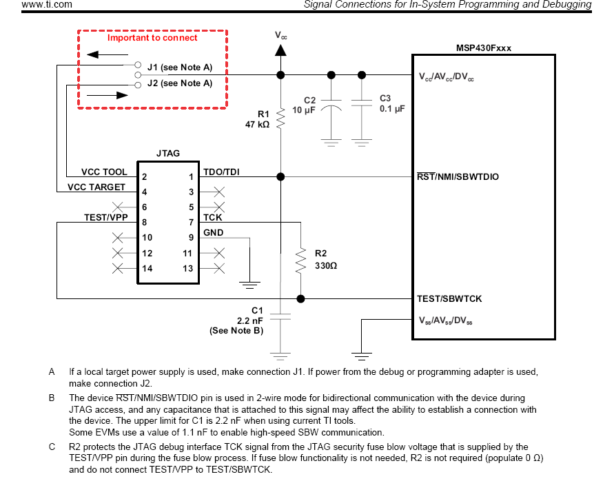
TCK with 330 Ohms (see page 23 of slau278x).

Have people verified this to work?
Is it possible with the standard MSP-FET or MSP-FET430UIF?
Is it working reliably?

Thanks and regards!

  • Tom Dehler said:
    Have people verified this to work?
    Is it possible with the standard MSP-FET or MSP-FET430UIF?
    Is it working reliably?

    Yes, there are people that have verified this to work. It is definitely possible with the MSP-FET.

    However, I too doubt that MSP-FET works reliably to blow physical JTAG fuse this way. TI engineers have looked into this after other members of E2E reported difficulties in this usage of MSP-FET. They reported back that it works.  Personally, I think the 330 Ohms resistor to TCK pin needs to be replaced by a resistor of less resistance. This is a trade-off between protecting the TCK pin and being able to blow the fuse reliably.

  • Thanks for the answer. Hmm, I am new to all this stuff but if I get page 9 of slau320
    correctly, TCK only goes from JTAG to CPU. So how about using some Low Vf Shottky
    diode (e.g. BAT 60A) instead of the 330 ohms -- maybe together with an additional
    pull-down resistor?

    For me, reliability of this process is not that important but once the stuff gets handed
    over to the final manufacturer of the device, it has to work...

    As you emphasised the MSP-FET: Are there other interfaces which maybe work more
    reliably?

    Another option would be to blow the fuse before the CPU will be soldered (by using
    the 4 wire interface) but this will cost additional time and is error prone.

    Best would be if one could order it with the fuse already blown, so all this wouldn't
    be needed...
  • Hi Tom,

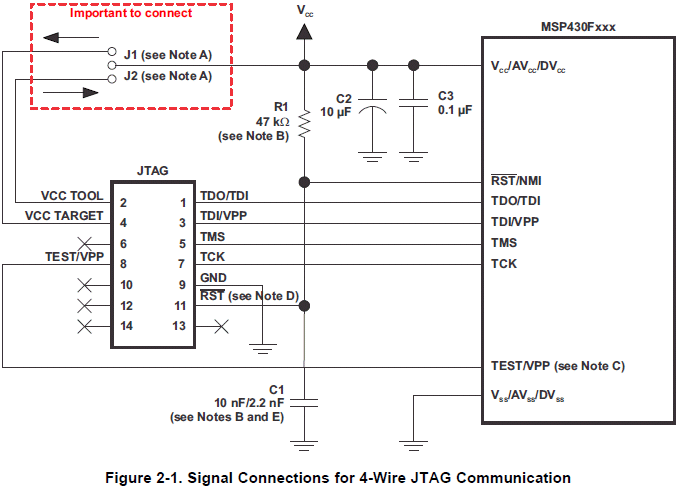
    MSP430F4152 has TEST / RESET pins, and can be programmed by SBW. Fuse can be blown by SBW too, because VPP is going to device TEST pin. MSP-FET has 2 separated VPP switches (ADG821BR), one for SBW (VF_TEST without any resistor on TEST pin) and another for JTAG (VF_TDI without any resistor on TDI pin), Maybe I am missing something, but don't see any problems regarding MSP430F4152 SBW programing and SBW fuse blowing. There is MSP-FET schematic in slau278 MSP430 Hardware Tools User's Guide. In slau320 there are also 2 separated VPP switches, one on TEST pin for SBW, and another on TDI pin for JTAG.


    In general SBW is slower than JTAG, but I boost it up with one extra wire, and it is faster then any other existing MSP430 JTAG tool.

  • > VF_TEST without any resistor on TEST pin

    Yes, but the resistor (sitting on the target board) will still be needed as it has to "combine" the TCK
    and TEST/VPP SBW signals. Of course, I'd prefer to integrate it into the programmer (or connector)
    so I won't need it on _every_ target board.

    > ... but don't see any problems regarding MSP430F4152 SBW programing and SBW fuse blowing

    :-) That was my impression as well but I preferred to ask and maybe gain some user experience.

    > In slau320 there are also 2 separated VPP switches

    Yes, I am pretty sure the programming hardware (no matter if it's MSP-FET, 430UIF or REP430F)
    is capable of doing it. My intention was to get some feedback from users actually using this
    as I found various indications giving the imagination it was not _that_ straight forward...

    > There is MSP-FET schematic in slau278

    I didn't focus on MSP-FET in the first way -- more on the older FET430UIF version as I don't use
    Windows and the UIF is told to work with Daniel Beer's mspdebug . But as the fuse eventually
    will only be blown at the production site I think using the MSP-FET together with Windows will
    be reasonable.

    Best would be if we could buy the cpus with an already blown fuse... No struggling with JTAG
    and all this stuff. Just hook up a BSL programmer and all would be well...
  • For SBW, your device has TEST pin, and doesn't need to "combine" it with TCK. This, what you are writing about is related to devices without TEST pin.  For SBW fuse blow, you don't need any extra resistor anywhere. It is same with FET430UIF or MSP-FET.

    If you don't want to use Windows, there is TI open source MSP Flasher that is working also on Linux / OS X.

    http://www.ti.com/tool/msp430-flasher

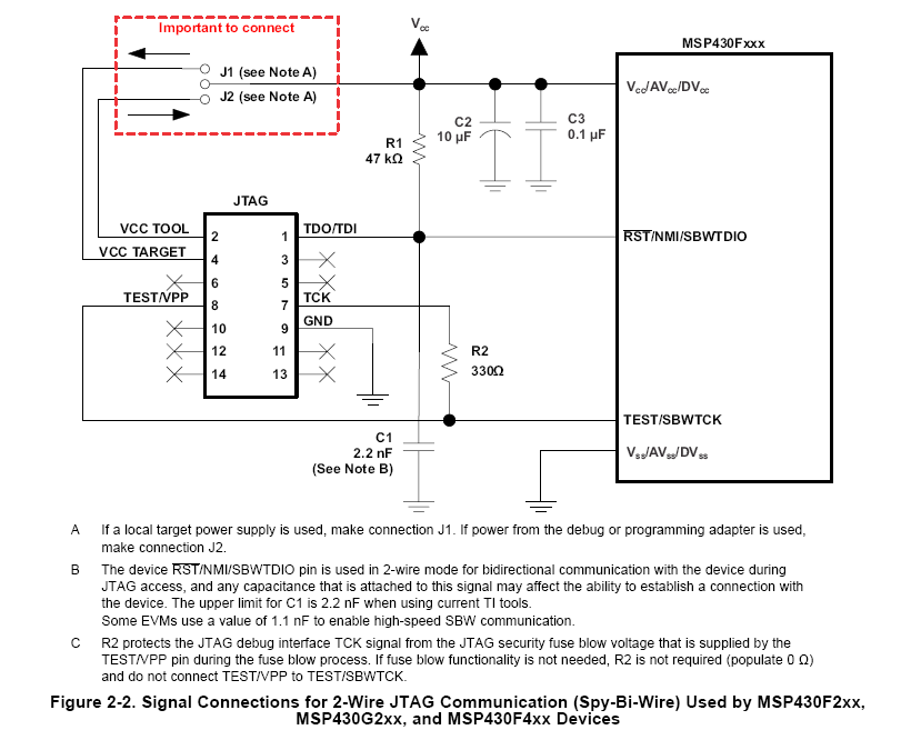
  • Maybe I haven't understood the whole SBW concept... The TEST/SBWTCK pin has IMHO two purposes: 1. Being the clock pin for the SBW interface and receiving the voltage for the fuse blow. This is why it is "combined" (as I call it ) by using the 330 ohms resistor here:

  • From my point of view, this picture from slau278 has correct connection for your device, for SBW (VPP on TEST pin) and JTAG (VPP on TDI pin), regarding communication and fuse blow. However, it is marked as for JTAG communication, not for SBW, so somebody from TI should clarify this.

  • > picture from slau278 has correct connection for your device, for SBW (VPP on TEST pin) and JTAG (VPP on TDI pin),

    No, not for SBW in my eyes. It's just for (4-wire) JTAG. The connection TEST/VPP is just for setting up the 4-wire JTAG.

    Unfortunateley, I cut away the footer of my pic, let's try again ;-)


    Here TEST/VPP is used to set up SBW communication (TEST) and to pass the fuse blowing voltage (VPP). However, for communicating with the device (once it has been set up) TCK is used. But both end on the same pin TEST/SBWTCK and this is why they have to be "combined" with the 330 ohms resistor.

    This is my "newbie" interpretation of things but it is quite possible that I still haven't got it correctly ;-)


  • Tom Dehler said:
    Here TEST/VPP is used to set up SBW communication (TEST) and to pass the fuse blowing voltage (VPP). However, for communicating with the device (once it has been set up) TCK is used. But both end on the same pin TEST/SBWTCK and this is why they have to be "combined" with the 330 ohms resistor.

    Almost correct, but read the foot note C of that Figure. The TCK pin of the FET-MSP is used to drive the SBWTCK of the target to set up SBW communication etc.. But it cannot deliver the final blow (a 6V pulse of 1 msec in duration). The TEST/VPP pin of the FET-MSP is used for that 1 msec only.

    Tom Dehler said:
    So how about using some Low Vf Shottky diode (e.g. BAT 60A) instead of the 330 ohms ...

    Good idea, that might work. The TEST/VPP pin of the FET-MSP is probably driven low (instead of being in a high-impedance neutral state0  

  • > The TCK pin of the FET-MSP is used to drive the SBWTCK of the target to set up SBW
    Ah, right, I mixed this up. So we can say: All "normal" SBW communication (setup and subsequent usage) is done by TCK, only the fuse-blowing voltage comes from TEST/VPP.

    > The TEST/VPP pin of the FET-MSP is probably driven low
    If it's driven low actively we need another diode coming from TEST/VPP. But this won't be a problem since these additional 0,2 V probably can be generated within the FET. And we might need some pulldown on the TEST/SBWCTK side to get well-defined conditions there. OK, these would be 3 additional parts instead of just a 330 ohms but it's probably a cleaner approach. If lines are kept short, it might even be placed within the FET so it won't be needed on every target board...
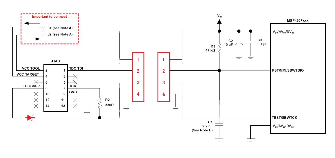
  • Almost. I thought of something like this:

  • That may be better.

    Could you or someone test this scheme? If so, I can make suggestions to get to the bottom of this. I do not the stuff needed to do it myself.
  • > Could you or someone test this scheme?

    I might, one day ;-). As I wrote initially, I am currently planning a design with the F4152. It is intended to replace a design containing a P325. Things are clear so far -- apart from the fact that programming is entirely different (the P325 is EPROM/OTP based and programming is done through the PRGS430 ;-)). And therefore I am currently concentrating on JTAG/SBW and the BSL...

    But currently I am also looking at the FR4133. It has no "high-voltage" fuse and in this case things would be easier.

    Another important issue is that I develop the software under FreeBSD and I will have to find a way to upload the programme into the FLASH/FRAM. Currently (for the P325), I did this with PRGS430 under qemu but I'd prefer a native way. Fuse-blowing is not that important as this will be done late at the factory (and they have Windows machines, of course).

    So, yes, I might test this one day but it will surely take a couple of weeks...
  • FET VPP is 6.5V, and minimum voltage for fuse blowing in datasheet is 6V. Maybe VPP with diode voltage drop will not be high enough for fuse blow.

    My SBW+ flasher use same TEST pin for SBWTCK and hardware fuse blow. I can inform you, in few months when it will be completed. PC side is open source and it is working on Win / Linux / OS X. I will test it soon with MSP430F41x2, and it is already tested with MSP430FR4133 (#4). Together with MSP430FR5739 (#3), MSP430FR5949 (#5) and MSP430FR5959 (#6) on SBW+ bus.

    C:\msp430>flash -f test_msp430fr4133.txt -p com9 -w -v -crc

    File: "test_msp430fr4133.txt"
    Address: 0C400  Words: 7680
    Size: 15360 bytes

    Get Device
    # JTID Fuse Device Core Hard Soft LotWafer DieX DieY
    3  91   OK   0381  1106  24   24  94AFAA04 1500 3300
    4  98   OK   F081  0906  20   10  A6BDA108 2B00 0C00
    5  99   OK   6181  1106  30   30  C1F22407 2B00 2200
    6  99   OK   6581  1106  30   30  E1271D07 2F00 1900

    Write
    Time: 83 ms  Speed: 180,4 KB/s

    Verify
    Time: 83 ms  Speed: 180,4 KB/s

    CRC
    File  #3   #4   #5   #6
    E103 E103 E103 E103 E103
    Time: 33 ms  Speed: 454,0 KB/s

    Release Device

    Total Time: 250 ms

    C:\msp430>

  • For F5xx, F6xx, and FRxx, there is no physical JTAG "Fuse". There is no need for VPP, and the emulated "Fuse" is reversible (i.e., can be "un-blown" after they are "blown".)

    For these devices, JTAG access can be locked (or limited) by the content of 2 "Signature" words stored in the non-volatile memory. In F5xx and F6xx, these JTAG "Signatures" are inside the protected "BSL-Flash". In FRxx, these JTAG "Signature" are in the unprotected FRAM below the Interrupt Vectors..
  • Yes,that's what I ment by writing: It has no "high-voltage" fuse and in this case things would be easier.
  • > Maybe VPP with diode voltage drop will not be high enough for fuse blow.
    The BAT60A should be OK for that. Vf should be < 0.2V @100mA. Ir is less than 1mA @6.5V

    > I can inform you, in few months when it will be completed.
    This sounds very interesting -- although "a few months" might be too late for me ( I plan to investigate flashing / fusing as soon as possible).

    > PC side is open source and it is working on Win / Linux / OS X.
    Does it use any TI libs for the low-level work or is everything self-contained?

    Care to elaborate a bit more ;-)? Will it be possible to buy the hardware as a ready-to-use device or how are the plans?
  • > For F5xx, F6xx, and FRxx, there is no physical JTAG "Fuse". There is no need for VPP, and the emulated "Fuse" is reversible (i.e., can be "un-blown" after they are "blown".)

    While we are at that: Can sombody confirm that "un-blowing" the
    fuse on a FR4133 works through (the locked) JTAG as well (for the
    price of an erased FRAM)?

    SLAU445d (MSP430FR4xx User's Guide) says on page 44:

    1.11.1 JTAG and SBW Lock Mechanism (Electronic Fuse)
    ...
    A device can be locked by writing any value other than 0000h or FFFFh to both JTAG Signature 1 and
    JTAG Signature 2. In this case, the JTAG and SBW interfaces grant access to a limited JTAG command
    set that restricts accessibility into the device. The only way to unlock the device in this case is t
    o use the BSL to overwrite the JTAG signatures with 0000h or FFFFh. Some JTAG commands are still poss
    ible when the device is secured, including the BYPASS command (see IEEE Std 1149-2001) and the
    JMB_EXCHANGE command, which allows access to the JTAG Mailbox System (see Section 1.10.4 for
    details).


    And SLAU320v (MSP430 JTAG User's Guide) says on page 58:

    1.4.4.2 FR4xx and FR2xx Devices
    The FR4xx and FR2xx device families do not support JTAG protection by a user-defined password. These
    device families have only a simple JTAG lock mechanism. If a JTAG lock signature is written to memory
    address 0xFF80, JTAG access is locked. To unlock these device families, a special erase command
    (User_Code_Erase 0x1A1A) must be applied through the JTAG mailbox (see the following detailed
    sequence diagram).


    I read this in a way that if the JTAG had been secured, I can hook up a SBW
    interface and send the above mentioned commands. Then the device gets
    erased entirely and I will have access to it by an unlocked JTAG (and a
    completely erased FRAM, of course).

    This way I don't need a BSL to update the FW of a device with a locked JTAG.

    Has somebody actually tried this on a FR4133?
  • Tom Dehler said:
    >
    This sounds very interesting -- although "a few months" might be too late for me ( I plan to investigate flashing / fusing as soon as possible).

    Does it use any TI libs for the low-level work or is everything self-contained?

    Care to elaborate a bit more ;-)? Will it be possible to buy the hardware as a ready-to-use device or how are the plans?

    On PC side, flasher is enumerated as CDC device, and PC sending commands directly to flasher. It is using native OS CDC drivers, there is no need to install anything on PC (except Win inf files). Just run complied PC program from command line (on Win / Linux / OS X). It is MSP-GANG like programmer, but it not related to any TI FET hardware / software solution and it is not compatible with any. Right now, I have only promotional boards without hardware fuse blow option.


    There is topic on 43oh and on last page you can find info about (un)blowing soft fuse on FRAM / Flash devices.

    http://forum.43oh.com/topic/2972-sbw-msp430f550x-based-programmer/?p=43889

  • Tom Dehler said:
     ... I plan to investigate flashing / fusing as soon as possible...

    Here is a plan to test the scheme.


    Step #1.

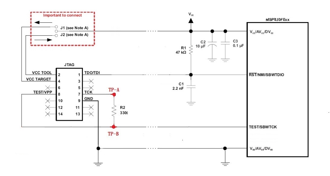
    Connect MSP-FET and the target as shown below.

    Please make the length of the 4 wires between the MSP-FET and the target short but practically possible for field use. Also bundle 4 wires the same way you would for field use.

    Note that MSP-FET pin 8 TEST/VPP is not connected to anything.

    Even without TEST/VPP connected, you should be able to use all the SBW operations except blowing the FUSE. Try a few of them (but not blowing the FUSE) and use an oscilloscope to examine the wave-forms at TP-A and TP-B. The wave-forms should be almost identical. Specifically, they normally should both high and very near Vcc. When they go low, they should be very near Vss. The frequency can be ~1 MHz (depends on the SBW software/firmware). The rise/fall time of the wave-forms should be fast enough at such frequency and beyond.


    Step #2.

    In this step, you add the connection from MSP-FET pin 8 TEST/VPP to TP-B as shown below.

    Again, try a few of SBW operations (but not blowing the FUSE) and use the oscilloscope to examine the wave-forms at TP-A and TP-B the same way as in Step #1 This time, you may find TP-B quite different and the SBW operation may not work or working not reliably. Specifically, I worry about the high level of TP-B not being close enough to Vcc.


    Step #3

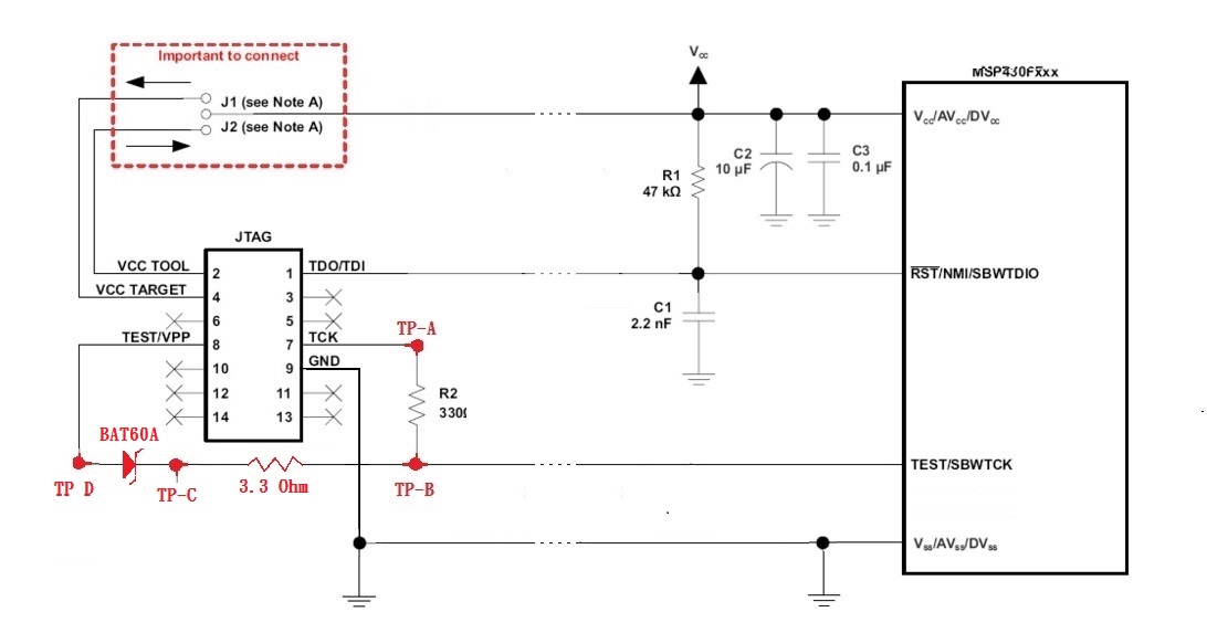
    We modify the connections again to include a BAT60A diode and a 3.3 Ohm resister. The resistor is not going to the final design. It is included during Step #4 to verify that (a) we still have margin for enough FUSE blowing voltage and (b) to act as a current probe to tell if and when the FUSE is blown.

    But during Step #3, we still do not try to blow the FUSE. We will repeat as in Step #1 & #2 to compare wave-forms of TP-A and TP-B.


    Step #4.

    I think we should review the results of Step #1, #2, and #3 before we actually try to blow the FUSE as we only get one chance per target chip to do so.

  • Sounds interesting, thanks! But:

    > There is topic on 43oh and on last page you can find info about (un)blowing soft fuse on FRAM / Flash devices.

    Yes, but if I read the post correctly, un-blowing is done by BSL. I want to do it by JTAG (SBW). This way, I don't have to deal with the BSL pins anymore.
  • This is related to FR5739. FR4xx can be unlocked (erased) by mailbox system.
  • > Here is a plan to test the scheme.
    I do not quite understand what you try to accomplish by adding the diode to the TEST/VPP wire. This way TEST/VPP is protected from TCK going high. But this was never an issue. TI added the 330 ohms in order to protect TCK from the 6.5V on TEST/VPP during fuse blowing. My intention was to replace the 330 ohms by the diode so we get known voltages on TEST/SBWTCK and no (or almost no) feedback to TCK while blowing the fuse. As I don't know what TEST/VPP does during "normal" SBW communications I suggested an additional diode there. It is probably unneeded since I expect TEST/VPP to be High-Z when not used (otherwise TI's version wouldn't work). My additional pull-down resistor is probably unneded since the device has an internal one.

    But if I decide to go the FR4133 path, all this is unneeded, fortunately ;-)
  • > FR4xx can be unlocked (erased) by mailbox system.
    Which is what I read from the mentioned PDFs and is now confirmed by you ;-)

    So we can say:

    A locked out JTAG interface on a FR4xx can be restored to full operation without knowing any passwords just by sending a couple of known commands through this (locked) JTAG interface. As a side effect, the FRAM will be erased. This way we can on one hand protect the software in the FRAM and on the other hand still update it to newer versions without the need of the BSL interface.

    May I ask: Have you tested this procedure with your programmer, by any chance?
  • Tom Dehler said:
    Yes, but if I read the post correctly, un-blowing is done by BSL. I want to do it by JTAG (SBW). This way, I don't have to deal with the BSL pins anymore.

    This is a classical Catch-22 situation. In order to use JTAG/SBW to un-lock, you need to have it un-locked to begin with.

  • >In order to use JTAG/SBW to un-lock, you need to have it un-locked to begin with.
    Did you actually read the 2 paragraphs I copied from the TI files (especially the second one, 1.4.4.2)?
  • Tom Dehler said:
    Did you actually read the 2 paragraphs I copied from the TI files (especially the second one, 1.4.4.2)?

    No, I did not read that. Shame on me.

    But I did read the previous revision of that document and I asked TI about this topic. I even made the subjugation about this. See: 

    e2e.ti.com/.../1640757

    The answer was, " I will take your comments into consideration and see what the team thinks." I did not expect that it is already done.

    I am happy about this.

  • old_cow_yellow said:
    No, I did not read that. Shame on me.

    ;-)

    But I did read the previous revision of that document and I asked TI about this topic. I even made the subjugation about this. See: 

    e2e.ti.com/.../1640757

    The answer was, " I will take your comments into consideration and see what the team thinks." I did not expect that it is already done.

    Unbelievable ;-)

    But given the fact that your discussion with TI was 2015-09-28 and the only thing that was changed in slau320v was something different (see revision history) and this only change happened after 2015-10-29, this all means that "consideration" and "implementation" happened within just one month ;-).

    Anyway, I will trust all this only after somebody confirms, that it actually works. If it does, it will be a step into the right direction as I won't need BSL hardware additionally to JTAG hardware to deal with the device

  • Just stumbled upon this entry in revisions.txt in MSPDebugStack:

    Rev 3.4.1.000
    ========================================================================
    04/24/2014 Alexander Festini / Florian Berenbrinker
     
        New device support:
        - MSP430FG6626
        - MSP430FR4133 Family
        - MSP430FR6989 Family
     
        New Features:
        - User code erase via JTAG mailbox on MSP430FR4133 family
    ...
    

    And in DLL430_v3/src/TI/DLL430/FramMemoryAccessFRx9.cpp of the MSPDebugStack we find:

    bool FramMemoryAccessFRx9<MPU>::erase(uint32_t start, uint32_t end, uint32_t block_size, int type)
    ...
                    el->appendInputData16(LONG_MAILBOX_MODE);       // Mailbox Mode
                    el->appendInputData16(STOP_DEVICE);                     // Data 1 Mailbox
                    el->appendInputData16(MAIN_ERASE_MODE);         // Data 2 Mailbox
    

    with STOP_DEVICE = 0xA55A and MAIN_ERASE_MODE = 0x1A1A...

    So next step will be to find out which programmes use libmsp430.so and will work under FreeBSD...

  • Tom Dehler said:
    May I ask: Have you tested this procedure with your programmer, by any chance?


    Not yet.

    Tom Dehler said:

    Just stumbled upon this entry in revisions.txt in MSPDebugStack:

    Rev 3.4.1.000
    ========================================================================
    04/24/2014 Alexander Festini / Florian Berenbrinker
     
        New device support:
        - MSP430FG6626
        - MSP430FR4133 Family
        - MSP430FR6989 Family
     
        New Features:
        - User code erase via JTAG mailbox on MSP430FR4133 family
    ...
    

    And in DLL430_v3/src/TI/DLL430/FramMemoryAccessFRx9.cpp of the MSPDebugStack we find:

    bool FramMemoryAccessFRx9<MPU>::erase(uint32_t start, uint32_t end, uint32_t block_size, int type)
    ...
                    el->appendInputData16(LONG_MAILBOX_MODE);       // Mailbox Mode
                    el->appendInputData16(STOP_DEVICE);                     // Data 1 Mailbox
                    el->appendInputData16(MAIN_ERASE_MODE);         // Data 2 Mailbox
    

    with STOP_DEVICE = 0xA55A and MAIN_ERASE_MODE = 0x1A1A...

    So next step will be to find out which programmes use libmsp430.so and will work under FreeBSD...

    It is also covered by slau320. There is EraseFRAMViaBootCode_430Xv2 function in JTAGfunc430FR.c that is called from Replicator430FR.c
    .
        // Uncomment the following section if the JTAG password is set and should be removed - FR4xx/FR2xx    
        /*if(GetDevice_430Xv2() == STATUS_FUSEBLOWN)
        {
            if (!EraseFRAMViaBootCode_430Xv2(MAIL_BOX_32BIT, STOP_DEVICE, USER_CODE_ERASE))   
            {
                ShowStatus(STATUS_ERROR, 2);
            }      
            // Check if main memory is completely erased.
            if (!EraseCheck_430Xv2(mainStartAdress, mainLength/2))   
            {
                ShowStatus(STATUS_ERROR, 2);
            }
        }*/

  • Not yet.

    OK, no problem. It will take a few days until I get my hands on a MSP-TS430PM64D anyway. But I already compiled your flash.zip with FreePascal succesfully on my system (FreeBSD-9.3). BTW, I found this flash.zip and bsl.zip and the manual.pdf on 43oh but didn't find a code for your programmer itself (well, I know it is not ready yet but since there are the pascal sources for the PC side I just wondered about the programmers firmware...).

    It is also covered by slau320.

    Yes, found this as well. But if I got things correctly, this is for use in that TI Replicator (which I don't need). Apart from that, I have compiled the msp430 debug stack already and the MSP430Flasher (both from TI) an my system. I will try to get some MSP-FET or MSP-FET430UIF and see if they work...

  • Tom Dehler said:
    BTW, I found this flash.zip and bsl.zip and the manual.pdf on 43oh but didn't find a code for your programmer itself (well, I know it is not ready yet but since there are the pascal sources for the PC side I just wondered about the programmers firmware...).

    Firmware is coded in assembler, and it is not open source. It is distributed in form of txt file that can be uploaded by CDC BSL (with AES) .

    Tom Dehler said:
    Yes, found this as well. But if I got things correctly, this is for use in that TI Replicator (which I don't need). Apart from that, I have compiled the msp430 debug stack already and the MSP430Flasher (both from TI) an my system. I will try to get some MSP-FET or MSP-FET430UIF and see if they work...

    Maybe this can be found in eZ-FET lite firmware source, and in this case it should work also with LP's

  • Firmware is coded in assembler, and it is not open source.

    I see, no problem (as long as it works ;-)).

    BTW, will it be mandatory to use the additional connection or can it be used in Standard-SBW mode with only SBWTDIO and SBWTCK as well? For various reasons, I want to minimise the amount of wires needed and speed is not important.

  • Tom Dehler said:

    BTW, will it be mandatory to use the additional connection or can it be used in Standard-SBW mode with only SBWTDIO and SBWTCK as well? For various reasons, I want to minimise the amount of wires needed and speed is not important.

    Flashing (F2xx /  F5xx / F6xx) can be done only by SBW+ (3 wires). FRAM devices can be used with standard SBW (2 wires) on lower speed, using Quick Read / Write commands. Flasher also have possibility to provide 2 CDC / Mailbox bridges, so it is possible to have logging from target 5xx / 6xx devices during free running without any extra wire.
    I tested MSP430FR4133 unlock, without BSL, and it is working.

    C:\msp430>flash -p com4 -f test_msp430fr4133.txt -w -v

    File: "test_msp430fr4133.txt"
    Address: 0C400  Words: 7680
    Size: 15360 bytes

    Get Device
    # JTID Fuse Device Core Hard Soft LotWafer DieX DieY
    1  98   OK   F081  0906  20   10  A6BDA108 2B00 0C00

    Write
    Time: 82 ms  Speed: 181,0 KB/s

    Verify
    Time: 83 ms  Speed: 180,3 KB/s

    Release Device

    Total Time: 203 ms

    C:\msp430>flash -p com4 -fuse

    Get Device
    # JTID Fuse Device Core Hard Soft LotWafer DieX DieY
    1  98   OK   F081  0906  20   10  A6BDA108 2B00 0C00

    Fuse Blow (Y/N)? y

    Release Device

    Total Time: 1550 ms

    C:\msp430>flash -p com4 -f test_msp430fr4133.txt -w -v

    File: "test_msp430fr4133.txt"
    Address: 0C400  Words: 7680
    Size: 15360 bytes

    Get Device
    # JTID Fuse
    1  98 Blown
    Error 101: Syncronization problem.

    Release Device

    Total Time: 32 ms

    C:\msp430>flash -p com4 -euc

    Erase User Code
    Time: 103 ms

    Total Time: 106 ms

    C:\msp430>flash -p com4 -f test_msp430fr4133.txt -w -v

    File: "test_msp430fr4133.txt"
    Address: 0C400  Words: 7680
    Size: 15360 bytes

    Get Device
    # JTID Fuse Device Core Hard Soft LotWafer DieX DieY
    1  98   OK   F081  0906  20   10  A6BDA108 2B00 0C00

    Write
    Time: 82 ms  Speed: 181,3 KB/s

    Verify
    Time: 83 ms  Speed: 180,5 KB/s

    Release Device

    Total Time: 203 ms

    C:\msp430>
  • Test from one cmd line without fuse blowing

    C:\msp430>flash -p com9 -f test_msp430fr4133.txt -w -v -euc -v

    File: "test_msp430fr4133.txt"
    Address: 0C400  Words: 7680
    Size: 15360 bytes

    Get Device
    # JTID Fuse Device Core Hard Soft LotWafer DieX DieY
    1  98   OK   F081  0906  20   10  A6BDA108 2B00 0C00

    Write
    Time: 82 ms  Speed: 181,4 KB/s

    Verify
    Time: 83 ms  Speed: 180,5 KB/s

    Release Device

    Erase User Code
    Time: 24 ms

    Get Device
    # JTID Fuse Device Core Hard Soft LotWafer DieX DieY
    1  98   OK   F081  0906  20   10  A6BDA108 2B00 0C00

    Verify
    # Address File Data
    1  0C400  CE21 FFFF
    Time: 85 ms  Speed: 175,6 KB/s

    Release Device

    Total Time: 344 ms

    C:\msp430>

  • Tom Dehler said:
    So next step will be to find out which programmes use libmsp430.so and will work under FreeBSD...

    SLAA685–December 2015, should have been the right kind of document to find the answer. No luck there!

  • I tested MSP430FR4133 unlock, without BSL, and it is working.


    Very interesting, thanks!

    flash -p com4 -euc


    I've check the lastest flash.zip from 43oh but didn't find an -euc arg. Probably the version there is just too old...

    It's good to know there is at least one programmer which can do the job I need: Programming an MSP430FR4133

    through SBW even if the JTAG is locked. Last thing to do is to port your FreePascal application to FreeBSD -- I can

    do that and send you the results. Of course, I'd need some programming hardware to test it. So the next question

    would be "How will your interesting work be made available for public consumption and when ;-)?".
     

  • old_cow_yellow said:
    Tom Dehler
    So next step will be to find out which programmes use libmsp430.so and will work under FreeBSD...

    SLAA685–December 2015, should have been the right kind of document to find the answer. No luck there!

    Of course I didn't expect TI to support their Code Composter on FreeBSD (and even if they did I wouldn't have used it). But I have made a port of their MSP430Flasher and I'll try it in the upcoming days...

  • Tom Dehler said:

    Last thing to do is to port your FreePascal application to FreeBSD -- I can do that and send you the results. Of course, I'd need some programming hardware to test it. So the next question would be "How will your interesting work be made available for public consumption and when ;-)?".

    It is tested on all Ubuntu versions, from 10.10 til 15.10. However, I can't tell that it will work on FreeBSD too, without testing it, first. Having working PC side, ported to another OS is one thing, and having completely working system is another. For example programmer can be stopped at enumeration because of some specific OS request, even PC side is compiled without errors, and working just fine. Than I can see (you can't) from programer logs what is going on.

    I will try to test it on FreeBSD next week. I have few boards, without hardware blow fuse option, that are ready for "public consumption". You can contact me by e2e PM.

  • zrno soli said:
    I will try to test it on FreeBSD next week.

    OK, I can help in case it's needed. I have compiled flash.zip from 43oh on FreeBSD-9.3 already -- this was an easy task.

    I have few boards, without hardware blow fuse option, that are ready for "public consumption". You can contact me by e2e PM.

    Don't need the (classic) fuse blow. Will try to get in touch with you...

**Attention** This is a public forum