


Other Parts Discussed in Thread: MSP430G2553
Hello,
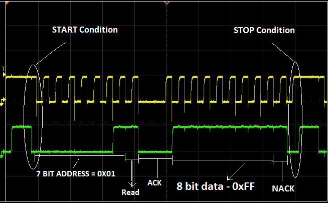
I just want to check the I2C communication between the two MSP430G2 (MSP430G2553) launchpads. When I am trying to configure master as transmitter and slave as receiver , slave acknowledges the data and address. But I am trying to configure master as receiver and slave as transmitter, master never acknowledges the data . Waveform will be like
I used example code with some minor modifications.
Master Receiver:
#include <msp430.h>
unsigned char RXData;
int main(void)
{
WDTCTL = WDTPW + WDTHOLD; // Stop WDT
P1SEL |= BIT6 + BIT7; // Assign I2C pins to USCI_B0
P1SEL2|= BIT6 + BIT7; // Assign I2C pins to USCI_B0
UCB0CTL1 |= UCSWRST; // Enable SW reset
UCB0CTL0 = UCMST + UCMODE_3 + UCSYNC; // I2C Master, synchronous mode
UCB0CTL1 = UCSSEL_2 + UCSWRST; // Use SMCLK, keep SW reset
UCB0BR0 = 12; // fSCL = SMCLK/12 = ~100kHz
UCB0BR1 = 0;
UCB0I2CSA = 0x001; // Slave Address is 01h
UCB0CTL1 &= ~UCSWRST; // Clear SW reset, resume operation
IE2 |= UCB0RXIE; // Enable RX interrupt
while (1)
{
while (UCB0CTL1 & UCTXSTP); // Ensure stop condition got sent
UCB0CTL1 |= UCTXSTT; // I2C start condition
while (UCB0CTL1 & UCTXSTT); // Start condition sent?
UCB0CTL1 |= UCTXSTP; // I2C stop condition
__bis_SR_register(CPUOFF + GIE); // Enter LPM0 w/ interrupts
}
}
// USCI_B0 Data ISR
#pragma vector = USCIAB0TX_VECTOR
__interrupt void USCIAB0TX_ISR(void)
{
RXData = UCB0RXBUF; // Get RX data
__bic_SR_register_on_exit(CPUOFF); // Exit LPM0
}
Slave Transmitter:
#include <msp430.h>
unsigned char TXData;
int main(void)
{
WDTCTL = WDTPW + WDTHOLD; // Stop WDT
P1DIR |= BIT0; // P1.0 output
P1SEL |= BIT6 + BIT7; // Assign I2C pins to USCI_B0
P1SEL2|= BIT6 + BIT7; // Assign I2C pins to USCI_B0
UCB0CTL1 |= UCSWRST; // Enable SW reset
UCB0CTL0 = UCMODE_3 + UCSYNC; // I2C Slave, synchronous mode
UCB0I2COA = 0x01; // Own Address is 01h
UCB0CTL1 &= ~UCSWRST; // Clear SW reset, resume operation
UCB0I2CIE |= UCSTTIE; // Enable STT interrupt
IE2 |= UCB0TXIE; // Enable TX interrupt
TXData = 0xff; // Used to hold TX data
while (1)
{
__bis_SR_register(CPUOFF + GIE); // Enter LPM0 w/ interrupts
}
}
// USCI_B0 Data ISR
#pragma vector = USCIAB0TX_VECTOR
__interrupt void USCIAB0TX_ISR(void)
{
UCB0TXBUF = TXData; // TX data
__bic_SR_register_on_exit(CPUOFF); // Exit LPM0
}
// USCI_B0 State ISR
#pragma vector = USCIAB0RX_VECTOR
__interrupt void USCIAB0RX_ISR(void)
{
UCB0STAT &= ~UCSTTIFG; // Clear start condition int flag
}
Please help me to know why the data received by the master is not acknowledged . And Let me know if there is any corrections as soon as possible

