Hey Guys,
I am trying to implement a "button pressed" detection via PMAP and Timer_A1 but the Timer_a1 doesn't jump in the appropriate ISR, in fact doesn't realize there's an interrupt at all, so I wanted to ask, if somebody sees my fault here:
I have a button connected to P2.6. when I am pushing the button it grounds P2.6. So I first configured P2.6 as a Input with Pull Up. When I now push the button the processor jumps in the appropriate ISR of the PORT2_IRQHandler. In the ISR I remap P2.6 to service CCI1A for Timer_A1, so that when I release the button a CC interrupt is generated when P2.6 goes high again. Maybe there is the problem: When I remap P2.6 to serve as CCI1A I also reconfigure the Port as an input with primary periphral module function (driverLib API). Is it possible, that the Pull Up is therefore disabled, so that there will not be a transistion from GND to Vcc?
Here are my Timer_A1 configuration structs and the ISrs:
/* Timer_A1 for BUTTON0_MSP432 detection */
const Timer_A_ContinuousModeConfig TimerButton0ConConfig =
{
		TIMER_A_CLOCKSOURCE_ACLK,           // ACLK Clock Source
        TIMER_A_CLOCKSOURCE_DIVIDER_2,       // ACLK/2 = 16,384kHz
        TIMER_A_TAIE_INTERRUPT_DISABLE,      // Disable Timer ISR
        TIMER_A_SKIP_CLEAR                   // Skup Clear Counter
};

const Timer_A_CaptureModeConfig TimerButton0CapConfig =
{
		TIMER_A_CAPTURECOMPARE_REGISTER_1,		// Using CCI1A
		TIMER_A_CAPTUREMODE_RISING_EDGE,		// rising edge selection
		TIMER_A_CAPTURE_INPUTSELECT_CCIxA,		// CCI1A select
		TIMER_A_CAPTURE_SYNCHRONOUS,				// no race condiction possible
		TIMER_A_CAPTURECOMPARE_INTERRUPT_ENABLE,	// enable interupt
		TIMER_A_OUTPUTMODE_OUTBITVALUE            // Output bit value
};
ISRs:
/**
* \brief PORT2 ISR
* \author Benjamin Brammer
* \date 15.07.16
*
* This interrupt is triggered if BUTTON0_MSP432 or
* BUTTON1_MSP432 is pressed. It either starts the button-pressed
* detection routine via Timer_A1 or just sets an event marker.
*/
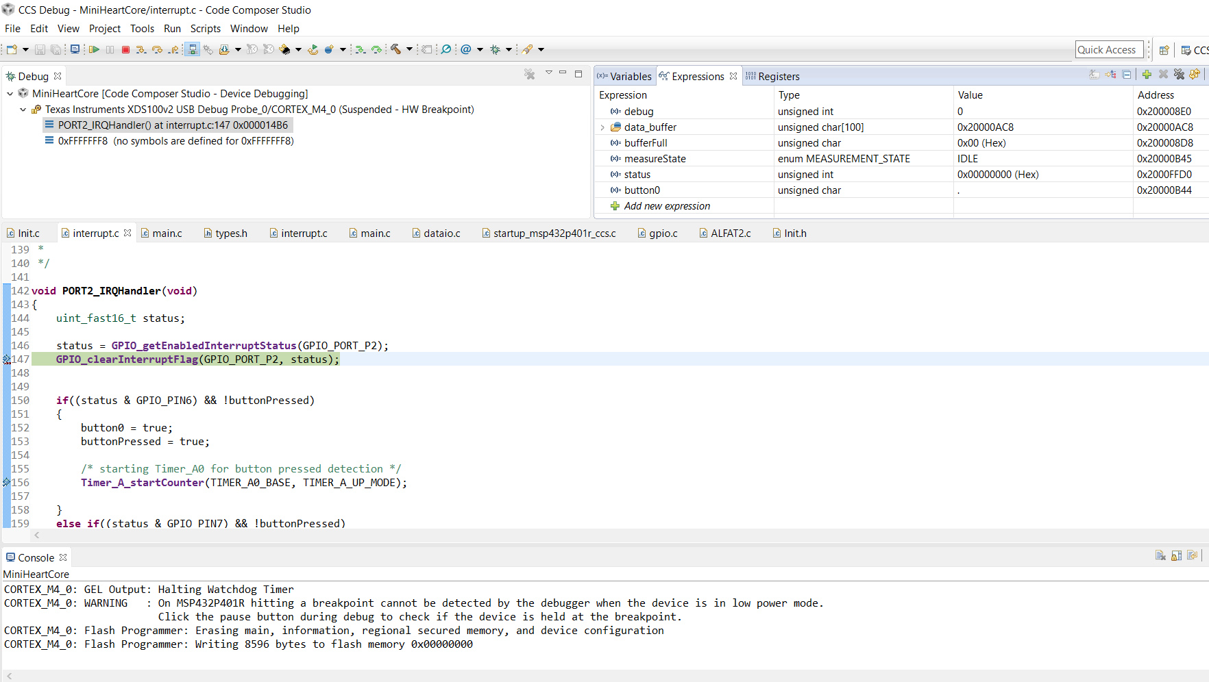
void PORT2_IRQHandler(void)
{
uint32_t status;
status = MAP_GPIO_getEnabledInterruptStatus(GPIO_PORT_P2);
MAP_GPIO_clearInterruptFlag(GPIO_PORT_P2, status);
if(status & GPIO_PIN6)
{
PMAP_configurePorts((const uint8_t *) port_mapping2, PMAP_P2MAP, 1,
PMAP_ENABLE_RECONFIGURATION);
GPIO_setAsPeripheralModuleFunctionInputPin(GPIO_PORT_P2,
GPIO_PIN6, GPIO_PRIMARY_MODULE_FUNCTION);
Timer_A_enableCaptureCompareInterrupt(TIMER_A1_BASE,TIMER_A_CAPTURECOMPARE_REGISTER_1);
Interrupt_enableInterrupt(INT_TA1_N);
Timer_A_startCounter(TIMER_A1_BASE, TIMER_A_CONTINUOUS_MODE);
}
//GPIO_disableInterrupt(GPIO_PORT_P2, GPIO_PIN6 |
// GPIO_PIN7);
}
/**
* \brief Timer_A1_CapComp ISR
* \author Benjamin Brammer
* \date 27.07.16
*
* This interrupt checks if a correct button press has
* been detected. Therfore if the button is released this ISR
* is triggered and compares the CCIA1 Value with the expected value
* for 1 second pressing. If a true press has been detected, the
* apropriate routine is executed, depending on the measurement state.
*
*/
void TA1_N_IRQHandler(void)
{
uint_fast16_t timerAcaptureValue;
Timer_A_clearCaptureCompareInterrupt(TIMER_A1_BASE,
TIMER_A_CAPTURECOMPARE_REGISTER_1);
timerAcaptureValue = Timer_A_getCaptureCompareCount(TIMER_A1_BASE,
TIMER_A_CAPTURECOMPARE_REGISTER_1);
if (measureState == IDLE && (timerAcaptureValue >= BUTTON_PRESS_COUNT))
{
measureState = INIT;
BOARD_LED_MEASURE_START_ON;
Timer_A_stopTimer(TIMER_A1_BASE);
}
else if (measureState == ACTIVE && (timerAcaptureValue >= BUTTON_PRESS_COUNT))
{
measureState = FINISH;
}
/* remaping P2.6 as an GPIO Input for BUTTON0_MSP432 press detection */
PMAP_configurePorts((const uint8_t *) port_mapping3, PMAP_P2MAP, 1,
PMAP_ENABLE_RECONFIGURATION);
GPIO_setAsInputPinWithPullUpResistor(GPIO_PORT_P2, GPIO_PIN6 |
GPIO_PIN7);
}
best regards
Benni