This thread has been locked.

If you have a related question, please click the "Ask a related question" button in the top right corner. The newly created question will be automatically linked to this question.

ADC12 - UART interaction MSP430F5438A

Other Parts Discussed in Thread: MSP430F5438A

Hello,

I am trying to make a code in order to read a value from the ADC12 of my msp430F5438A, and send this value through the UART port and visualize it in a LABVIEW program on my Computer. 

The LABVIEW do not receive any data, but if I test other code with nly a TImer and UART, the program show the received data. I am thinking that this problem is due to the code is not correct.

Can someone help me to check if this code is sending data?

#include <msp430.h>
#define ADC_UART_CONV 0.0622710622710623  //Convert ADC value in order to use with UARTBUF
int ADC_IN=0; //ADC Value
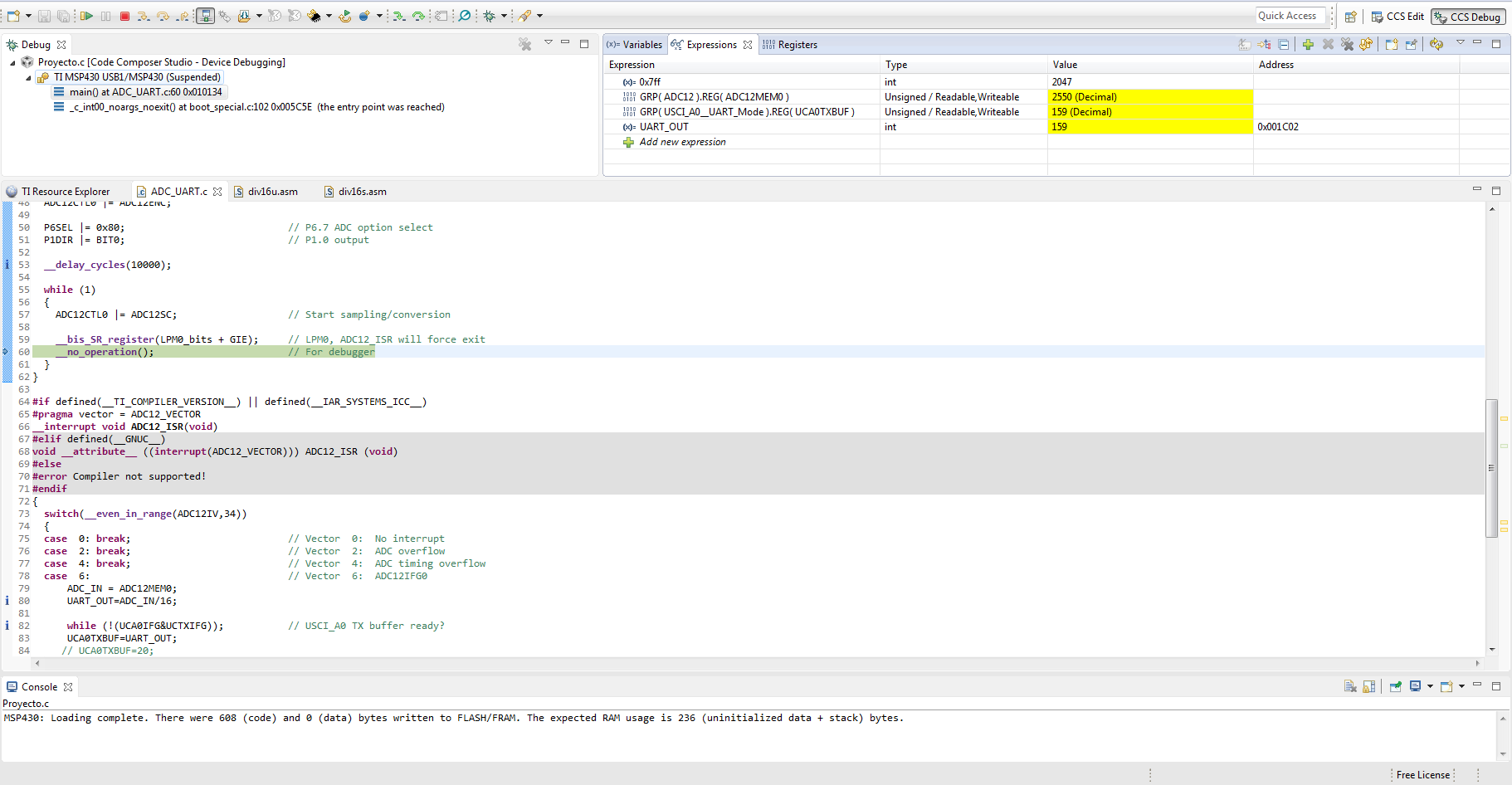
int UART_OUT=0; //Uart value after conversion
int main(void)
{
  WDTCTL = WDTPW + WDTHOLD;                 // Stop WDT
  //Configuración Timer
    TA0CCTL1 = CCIE;                          // CCR1 interrup enabled
    TA0CCR0 = 3277-1;  //100ms
    //TA0CCR1 = 16384;
    TA0CTL = TASSEL_1 + MC_1 + TACLR + TAIE ;         // ACLK, upmode, clear TAR
  //Configuración UART
    UCA0CTL1 |= UCSWRST;                      // **Put state machine in reset**
    UCA0CTL1 |= UCSSEL_2;                     // SMCLK
    UCA0BR0 = 6;                              // 1MHz 9600 (see User's Guide)
    UCA0BR1 = 0;                              // 1MHz 9600
    UCA0MCTL = UCBRS_0 + UCBRF_13 + UCOS16;   // Modln UCBRSx=0, UCBRFx=0,
                                              // over sampling
    UCA0CTL1 &= ~UCSWRST;                     // **Initialize USCI state machine**
    //Configuración ADC
    ADC12CTL0 = ADC12SHT02 + ADC12ON;         // Sampling time, ADC12 on
    ADC12CTL1 = ADC12SHP;                     // Use sampling timer
    ADC12IE = 0x01;                           // Enable interrupt
    ADC12MCTL0 |= ADC12INCH_7;
    ADC12CTL0 |= ADC12ENC;
  
    P6SEL |= 0x80;                            // P6.7 ADC option select
    P1DIR |= BIT0;                            // P1.0 output
    __delay_cycles(10000);
  while (1)
  {
    ADC12CTL0 |= ADC12SC;                   // Start sampling/conversion
    
    __bis_SR_register(LPM0_bits + GIE);     // LPM0, ADC12_ISR will force exit
    __no_operation();                       // For debugger
  }
}
// Timer0 A1 interrupt service routine
#pragma vector = TIMER0_A1_VECTOR
__interrupt void Timer0_A1_ISR( void )
{
  switch( TA0IV ) // Read interrupt vector for TA0
  {
    case 0: // No interrupt pending
    {
      break;
    }
    case 2: // TA0CCR1
    {
  // P1OUT = 0x03;                            // Toggle  P1.1
      break;
    }
    case 4: // TA0CCR2
    {
      break;
    }
    case 6: // TA0CCR3
    {
      break;
    }
    case 8: // TA0CCR4
    {
      break;
    }
    case 14: // Overflow - TA0IFG
    {
    while (!(UCA0IFG&UCTXIFG)); // USCI_A0 TX buffer ready?
     UCA0TXBUF=16;
     }
      break;
    }
  }
#if defined(__TI_COMPILER_VERSION__) || defined(__IAR_SYSTEMS_ICC__)
#pragma vector = ADC12_VECTOR
__interrupt void ADC12_ISR(void)
#elif defined(__GNUC__)
void __attribute__ ((interrupt(ADC12_VECTOR))) ADC12_ISR (void)
#else
#error Compiler not supported!
#endif
{
  switch(__even_in_range(ADC12IV,34))
  {
  case  0: break;                           // Vector  0:  No interrupt
  case  2: break;                           // Vector  2:  ADC overflow
  case  4: break;                           // Vector  4:  ADC timing overflow
  case  6:   // Vector  6:  ADC12IFG0
 ADC_IN = ADC12MEM0; //ADC value stored
 UART_OUT=ADC_IN*ADC_UART_CONV; // Conversion 
/*
 while (!(UCA0IFG&UCTXIFG)); // USCI_A0 TX buffer ready?
 UCA0TXBUF=UART_OUT;
*/
   if (ADC12MEM0 >= 0x7ff)                 // ADC12MEM = A0 > 0.5AVcc?
     P1OUT |= BIT0;                        // P1.0 = 1
   else
     P1OUT &= ~BIT0;                       // P1.0 = 0
   __bic_SR_register_on_exit(LPM0_bits);   // Exit active CPU
 break;
  case  8: break;                           // Vector  8:  ADC12IFG1
  case 10: break;                           // Vector 10:  ADC12IFG2
  case 12: break;                           // Vector 12:  ADC12IFG3
  case 14: break;                           // Vector 14:  ADC12IFG4
  case 16: break;                           // Vector 16:  ADC12IFG5
  case 18: break;                           // Vector 18:  ADC12IFG6
  case 20: // Vector 20:  ADC12IFG7
 break;
  case 22: break;                           // Vector 22:  ADC12IFG8
  case 24: break;                           // Vector 24:  ADC12IFG9
  case 26: break;                           // Vector 26:  ADC12IFG10
  case 28: break;                           // Vector 28:  ADC12IFG11
  case 30: break;                           // Vector 30:  ADC12IFG12
  case 32: break;                           // Vector 32:  ADC12IFG13
  case 34: break;                           // Vector 34:  ADC12IFG14
  default: break; 
  }
}

 Thanks in advance

  • Hello Miguel,

    The code you provided comments out the ADC12 conversion to UCA0TXBUF, but otherwise the code is continuously entering the ADC ISR and should be sending data. Your conversion from ADC_IN to UART_OUT however uses an ADC_UART_CONV floating constant of 0.0623 that conflicts with the integer type of ADC_IN. This most likely results in UART_OUT values of zero. You'd be much better off using an ADC_UART_CONV value of 16 and dividing ADC_IN by that instead (i.e. UART_OUT=ADC_IN/16). Then you will probably be able to send raw data values to LabView.

    Regards,
    Ryan
  • Hello Ryan,

    before everything thnaks for your fast answer.

    The operation that you describe has been modified. In the watch expression I can see the UCA0TXBUF data is correct, instead I can not  see the data in LABVIEW.

    In the code, I removed the timer and the code is the modified code is the next:

    #include <msp430.h>
    int ADC_IN=0;
    int UART_OUT=0;
    int main(void)
    {
      WDTCTL = WDTPW + WDTHOLD;                 // Stop WDT
      //UART configuration
        UCA0CTL1 |= UCSWRST;                      // **Put state machine in reset**
        UCA0CTL1 |= UCSSEL_2;                     // SMCLK
        UCA0BR0 = 6;                              // 1MHz 9600 (see User's Guide)
        UCA0BR1 = 0;                              // 1MHz 9600
        UCA0MCTL = UCBRS_0 + UCBRF_13 + UCOS16;   // Modln UCBRSx=0, UCBRFx=0,
                                                  // over sampling
        UCA0CTL1 &= ~UCSWRST;                     // **Initialize USCI state machine**
        //ADC12 configuration
      ADC12CTL0 = ADC12SHT02 + ADC12ON;         // Sampling time, ADC12 on
      ADC12CTL1 = ADC12SHP;                     // Use sampling timer
      ADC12IE = 0x01;                           // Enable interrupt
      ADC12MCTL0 |= ADC12INCH_7;
      ADC12CTL0 |= ADC12ENC;
      
      P6SEL |= 0x80;                            // P6.7 ADC option select
      P1DIR |= BIT0;                            // P1.0 output
      __delay_cycles(10000);
      while (1)
      {
        ADC12CTL0 |= ADC12SC;                   // Start sampling/conversion
        
        __bis_SR_register(LPM0_bits + GIE);     // LPM0, ADC12_ISR will force exit
        __no_operation();                       // For debugger
      }
    }
    #if defined(__TI_COMPILER_VERSION__) || defined(__IAR_SYSTEMS_ICC__)
    #pragma vector = ADC12_VECTOR
    __interrupt void ADC12_ISR(void)
    #elif defined(__GNUC__)
    void __attribute__ ((interrupt(ADC12_VECTOR))) ADC12_ISR (void)
    #else
    #error Compiler not supported!
    #endif
    {
      switch(__even_in_range(ADC12IV,34))
      {
      case  0: break;                           // Vector  0:  No interrupt
      case  2: break;                           // Vector  2:  ADC overflow
      case  4: break;                           // Vector  4:  ADC timing overflow
      case  6:   // Vector  6:  ADC12IFG0
     ADC_IN = ADC12MEM0;
     UART_OUT=ADC_IN/16;
     while (!(UCA0IFG&UCTXIFG)); // USCI_A0 TX buffer ready?
     UCA0TXBUF=UART_OUT;
       if (ADC12MEM0 >= 0x7ff)                 // ADC12MEM = A0 > 0.5AVcc?
         P1OUT |= BIT0;                        // P1.0 = 1
       else
         P1OUT &= ~BIT0;                       // P1.0 = 0
       __bic_SR_register_on_exit(LPM0_bits);   // Exit active CPU
     break;
      case  8: break;                           // Vector  8:  ADC12IFG1
      case 10: break;                           // Vector 10:  ADC12IFG2
      case 12: break;                           // Vector 12:  ADC12IFG3
      case 14: break;                           // Vector 14:  ADC12IFG4
      case 16: break;                           // Vector 16:  ADC12IFG5
      case 18: break;                           // Vector 18:  ADC12IFG6
      case 20: // Vector 20:  ADC12IFG7
     break;
      case 22: break;                           // Vector 22:  ADC12IFG8
      case 24: break;                           // Vector 24:  ADC12IFG9
      case 26: break;                           // Vector 26:  ADC12IFG10
      case 28: break;                           // Vector 28:  ADC12IFG11
      case 30: break;                           // Vector 30:  ADC12IFG12
      case 32: break;                           // Vector 32:  ADC12IFG13
      case 34: break;                           // Vector 34:  ADC12IFG14
      default: break; 
      }
    }
    the code is correct?

    which do you think the problem is?

    Regards,

    Miguel

  • Hi Miguel,

    You've already confirmed successful UART communication so if the value loaded into UCA0TXBUF is correct then I do not doubt that you are sending data to the host PC. You can try using another terminal, such as Tera Term or Hyperterminal, to confirm incoming bytes. Don't forget that raw data is being sent as compared to formatted data, I don't know what you are hoping to see in LabView but I know with other terminal programs that the incoming data is represented as its ASCII equivalent and not the decimal value that you might be expecting. Specific LabView questions should be asked on a NI-specific forum, since the MSP430 appears to be operating as intended.

    Regards,
    Ryan
  • Hi Ryan,
    Thanks for everything. I will try to check the data with other program.
  • Hi Ryan,

    I tried to check the flow data with a terminal program like you say me (Tera term), but the program no received data. On the other hand, with other different code, the program shows the input data. 

    In the next picture you can see how the UCA0TXBUF has information, but this data is not send.

    The code which has a correct functioning not has ADC, only it is a UART and Timer.

    what do you thing?

    Thanks in advance,

    Miguel

  • If you were to step through the line UCA0TXBUF=UART_OUT; does the character get sent through the terminal? Can you show the UCA0TXBUF register being populated with the UART_OUT value but then failing to be sent? Try setting UART_OUT to ASCII letter A (0x41) or anything else less than 128 and see if that shows up on the terminal.

    Regards,
    Ryan
  • The result is the same, the code does not send information. 

    In the first picture you can see the code which not work. In the second one, the case which I said you previously.

  • Where is your P3SEL initialization for BIT4 (UCA0TXD) and BIT5 (UCA0RXD)? This is required for UART communication but I don't understand how you are receiving characters through the Timer ISR without it.

    Regards,
    Ryan
  • Thank you very much, the problem was the initialization of the Pins TX and RX. Simple mistake... 

**Attention** This is a public forum