Because of the Thanksgiving holiday in the U.S., TI E2E™ design support forum responses may be delayed from November 25 through December 2. Thank you for your patience.

This thread has been locked.

If you have a related question, please click the "Ask a related question" button in the top right corner. The newly created question will be automatically linked to this question.

MSP432 Factory Reset Causing Error

Other Parts Discussed in Thread: MSP432WARE

Hello,

Regarding the REV C micros (XMS432P401R), we have had a reoccurring issue of boards becoming bricked after the Factory Reset process is performed described here (http://www.ti.com/lit/ug/slau575e/slau575e.pdf

After performing the Factory Reset, we are unable to load custom code onto the boards, but are always able to factory reset the boards once again (this code has been tested on other identical boards and fully functional, also various other sample codes have been tested with identical results).  The error code is shown below. 

Is there any particular most up to date Factory Reset GEL file.  We are currently programming our boards with the MSP432 RED launchpad using the XDS110 10 pin ARM connector output. Electrically we have 5 wires (TDI/TDO/TCK/TMS/GND) connected from our Launchpad to the custom board.  Are there any pulldown/pullup resistors needed on these lines? Didn't see anything on the launchpad schematic to indicate this. Since we are consistently able to factory reset the boards, I would assume our connection is correct but I am out of ideas as to what could be the issue..

We are using the most up to date version of CCS (6.1.3.00034) along with all the most recent updates, MSP432 DriverLib 3.21.0.05 and MSP432ware IDE Client/Target Content 3.40.0.25.

ERROR:

Error connecting to the target:
(Error -1063 @ 0x0)
Device ID is not recognized or is not supported by driver. Confirm device and debug probe configuration is correct, or update device driver.
(Emulation package 6.0.407.3)

Device is not accessible.
Reset the device to factory settings?


  • Hi Robert,

    Thanks for sharing the details about your software versions. Referring to the XMS432 Support wiki page, they seem to be ok.

    I have two initial questions. Are you power cycling between performing the Factory Reset and trying to load your custom code onto the board? Have you enabled password protection for the Factory Reset?

    Regards,

    James

    MSP Customer Applications

  • Hi James,


    Thank you for your prompt response.  We are power cycling between Factory Resets. (chronological order of events: launched target configuration (brand new empty project chosen for target config), connected to target, factory reset performed, terminated debug session (clicked stop button in CCS), powered off launchpad, powered off custom board, wait 10 seconds, powered up custom board, powered up launchpad, tried uploading code to the launchpad with debug, and then we received the error listed in my first post.

    We have also not enabled password protection for the Factory Reset.


    Best,

    Robert

  • Hi Robert,

    Thanks for the details about your programming method - it's very helpful for effective debugging.

    I'm wondering if there's an issue caused by the custom board (target) powering up before the LaunchPad (debugger). Could you try keeping power supplied to the LaunchPad while power cycling the custom board? Also, are you powering these from the same PC via USB?

    Using CCS v6.1.3, I took two red (XMS432 RevC) MSP432 LaunchPads and tried to duplicate your issue. For the debugger LaunchPad (board on the left), I powered it from my PC via USB and removed all jumpers from J101. For the target LaunchPad (board on the right), I powered it from a separate external power supply (two AA batteries) and removed all jumpers from J101. Next, I used a 10-pin ribbon cable to connect the two boards: XDS110 Out ----> MSP432 In

    In CCS, I opened the "msp432p401x_1" Toggle P1.0 code example project from MSP432Ware v3.50.00.02. First, I programmed the target board with this code example. After stopping the debug session, I went through the Factory Reset procedure. After stopping the debug session and removing the external power supply from the target board, I powered it back up and reprogrammed the Toggle P1.0 code example without encountering any errors. Try this approach and let me know if the error still occurs, and we can dig deeper.

    I've included my installation details for your reference.

    Regards,

    James

    MSP Customer Applications

  • Hi James,


    I just tried keeping the power supplied to the LaunchPad while power cycling the custom board with no luck.  I am powering the custom board from an external DC power supply and powering the Launchpad from a PC via USB.

    I tried your exact setup shown above with two REV C launchpads and it works without a problem.  I am starting to wonder if it has anything to do with our programming connection (even though I am able to Factory Reset the board..). Here (https://e2e.ti.com/support/microcontrollers/msp430/f/166/p/1978984/reply?ReplyToContentTypeID=1 ) it mentions that pull-down resistors are required for JTAG.  Currently we have pull-down resistors on all 4 lines (TCK,TDI,TDO,TMS) and we have been programming like this for quite some time without any issue, however it may be an issue for factory reset. With the first revision of the Launchpad (black) we found that we could not program our custom boards (SWD interface) without a pull-down on the SWCLK line.  From the launchpad schematic available online, it does not seem that these lines have any resistors but maybe you can confirm? Otherwise any other ideas?

    I have also attached my installation details below. Seems like the only difference is that you have a newer MSP432 target content 3.50.0.02. I assume this is not available to the public yet, since I tried to update it and it says no updates were found.

  • Hi Robert,

    Thanks for trying these recommendations. Regarding the pull-down resistors on the JTAG signals, could you provide the link again? Unfortunately, I wasn't able to access it. I noticed that these resistors aren't used on the LaunchPad, so I'm curious to see what this link says.

    Can you try changing the JTAG / SWD / cJTAG Mode Settings to "SWD Mode - Aux COM port is target TDO pin" under "Connection Properties"? When the settings of Port J are changed, full JTAG access is prevented on these pins. Using SWD allows access through the dedicated debug pins.

    Regards,

    James

    MSP Customer Applications

  • Hi James,

    My apologies, posted the wrong link earlier: www.support.code-red-tech.com/.../HardwareDebugConnections

    The JTAG / SWD / cJTAG Mode Settings are already set to "SWD Mode - Aux COM port is target TDO pin" under "Connection Properties". These have not been modified since the new REV C launchpads have been in use.

    When I test the connection, it states that "The SWD Mode Integrity test has succeeded".

    Best,
    Robert
  • Hi Robert,

    Thanks for confirming your Mode Settings. Would you be able to share the debug portion of your custom board schematic? Send me a private message if you're not able to. What specific connector/pins are you using on the LaunchPad debugger for the JTAG/SWD interface?

    Regards,

    James

    MSP Customer Applications

  • Hi James,

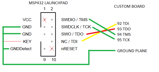
    Although we cannot share our official schematic on this forum, I can describe the debug portion of the schematic to you since it is very simple.  I went ahead and just now removed all of the pull down resistors on our custom board and we are still able to Factory Reset the boards with the previous procedure.  So the debug connection is as follows:

    We are directly connected from the launchpad's XDS110 debug pins to our custom board's JTAG pins.


    Best,

    Robert

  • Hi Robert,

    The debug connection diagram is helpful. How are you implementing your RESET circuit? For proper JTAG operation, the datasheet specifies a 47kOhm pull-up resistor and a 1.1nF pull-down capacitor, as shown below.

    This may be causing the issue. Let's keep the other pull-down resistors that you removed off for now.

    Regards,

    James

    MSP Customer Applications

  • Hi James,


    Does this reset circuit have anything to do with the nReset connection (pin 10) on the 10pin cortex debug connector? (nReset pin shown in my last post or on page 2 of http://infocenter.arm.com/help/topic/com.arm.doc.faqs/attached/13634/cortex_debug_connectors.pdf Or is this just an additional circuit needed on our board aside from the programming cable?  At the moment, I do not have the nReset pin connected to anything, which I am not quite sure is correct.

    Thank you,

    Robert

  • Hi Robert,

    Yes, the RSTn pin of the MSP432 should be pulled up to VCC using a 47kOhm resistor and pulled down to GND using a 1.1nF capacitor, as shown in my post above (which came from the MSP432 LaunchPad User's Guide) and discussed in Table 4-4 on page 27 of the MSP432 datasheet.

    Then, the RSTn pin of the MSP432 should be connected to the nRESET pin of the Cortex debug connector on your board to ensure proper JTAG/SWD operation.

    Regards,

    James

    MSP Customer Applications

  • Hi James,

    We added the 47kohm pull-up with 1.0nF pulldown to the RSTn pin of the MSP432 and then connected the nRESET pin of the Cortex debug connector to our board with no luck.  We are still able to factory reset the boards but unable to program.

    What do you recommend trying next?

    Best,

    Robert

  • Hi Robert,

    Thanks for trying this. Let's keep the reset circuit implemented moving forward. Since we're able to perform the Factory Reset and then program code on the target LaunchPad, the debugger LaunchPad seems to be fine. However, missing connections, wrong capacitance values, etc. could be causing the issue on the custom boards.

    I'd recommend comparing the schematic of your custom board to the schematic of the LaunchPad. It may be helpful to view the design files in Eagle. Another good reference would be the schematic of the MSP-TS432PZ100 target development board, which has a 10-pin Cortex debug connector and all connections/components for programming/debugging through JTAG interface or the Serial Wire Debug (SWD 2-wire JTAG) protocol. See Section 1.2 in the MSP432 Hardware Tools User's Guide for the proper jumper configurations.

    Regards,

    James

    MSP Customer Applications

  • This issue was handled off-line, but I wanted to close the loop here in case other community members encounter the same issue.

    In this case, a precision voltage reference was used as the AVCC supply and a low-noise LDO was used as the DVCC supply. Unfortunately, the start-up profiles between these two supplies differed more than the absolute maximum of +/- 0.3V (+/- 0.1V during startup), which is shown in Sections 5.1 and 5.3 in the datasheet. Per Footnote 2, voltage differences between DVCC and AVCC exceeding this limit may cause malfunctions of the device.

    To resolve the issue, the LDO was used to supply both AVCC and DVCC along with a series resistor between them to help filter noise.

    Regards,

    James

    MSP Customer Applications

**Attention** This is a public forum