This thread has been locked.

If you have a related question, please click the "Ask a related question" button in the top right corner. The newly created question will be automatically linked to this question.

MSP-GANG: Error while using the MSP -gang

Part Number: MSP-GANG
Other Parts Discussed in Thread: MSP-FET

Dear TI

I am using a designated board (target board) of my design and trying to program it using the MSP-GANG programmer.

I was successful programming the target board  with the MSP-FETFlash programmer a .Hex file in Command mode with no external power.

However, if I'm to use the MSP-GANG I'm getting a ERROR 23: MCU device initialization failed for some reason (see attached photo).

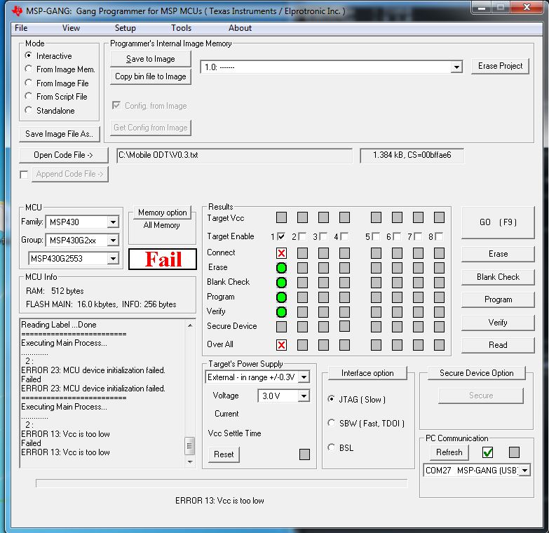
Thinking their is a problem with the supply voltage, i have used an external P.S and got a different error (see attached photo) ERROR:13 VCC is too low.

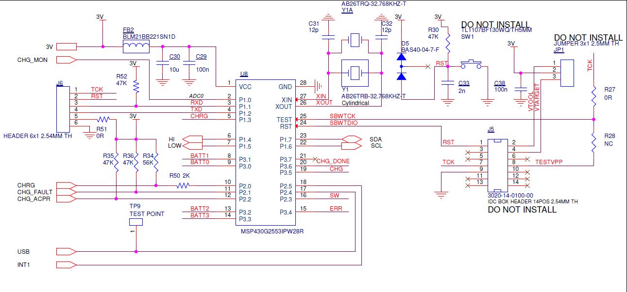
I've added the board schematic of the MCU

Can you please advise on the matter?

Thanks

Sharon .D.

  • Hi Sharon,

    Thank you for the detailed description of the issue you're experiencing. My first thought after the MSP-FET succeeded and the MSP-GANG failed was that the MSP was drawing too much current for the MSP-GANG to supply it. The max the MSP-GANG can supply is 30mA.

    I think you were right to switch to an external supply but, I want to ensure you have the hardware setup correctly for it. When using an external supply, make sure that you've disconnected the Vcc provided by the MSP-GANG to the target. Otherwise, this could cause power-supply conflicts that damage both the target device and the MSP-GANG. Also, ensure that the external supply for the target device is also connected to the Vextin (pin4) on the JTAG connector. This connection is how the MSP-GANG senses the external voltage supplied to the target device. 

    Finally, make sure the same voltage being used to power the target device is set in the MSP-GANG programmer. In the images above it looks like you've got it set to 3.0V. Be sure to change this if the external voltage differs. 

    Let me know if you have everything setup as described above, then we can explore more options if necessary.

    Best regards, 

    Caleb Overbay

  • Hi Sharon,

    Were you able to make any progress on this that you'd like to share?

    Best regards,
    Caleb Overbay
  • Hi Caleb
    Sorry for the late response.
    I have applied your suggestions, I have used an external P.S and shortened pins 2 and 3 in JP1 as you suggested.
    By doing so, the Jtag Pin #4 is now connected to the External P.S.
    To verify that the voltage is sufficient I connected a DVM to make sure that 3V does reach the MCU.
    Now, after those changes were set, I get a different error "ERROR 23: MCU device initialization failed."
    I have Viewed different suggestions (on the forums) regarding this error but none were suitable. the Interface options is set on "Jtag (slow)"
    Can you please advise on the matter?

    Thanks!
    Sharon .D.
  • Hi Sharon,

    In your schematic it looks like the connection is SBW and not JTAG. Try switching over to SBW communication and see if it works.

    Best regards,
    Caleb Overbay
  • Hi Calab!
    Thank you very much!

    It worked almost immediately (had to slow it down)
    You are awesome and I'm an idiot :-)


    Sharon .D.

**Attention** This is a public forum