This thread has been locked.

If you have a related question, please click the "Ask a related question" button in the top right corner. The newly created question will be automatically linked to this question.

Power consumption problem of msp430f6736' LCD_C Module

Part Number: MSP430F6736
Other Parts Discussed in Thread: MSP430WARE, ENERGYTRACE, MSP-FET

Dear,

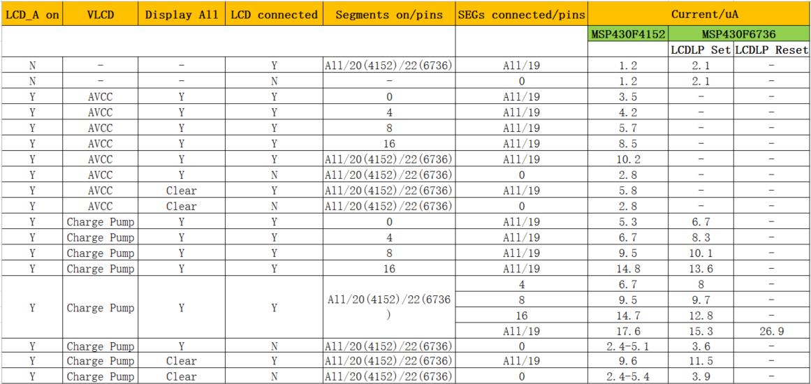
Recently, I use MSP430F6736' LCD_C Module to drive an LCD. But the power consumption of LCD is not low enough as expected. The test result as follows:


Test condition

Current

Unit

1

LPM3,LCD 4-mux mode,charge pump disabled,

No connect external LCD

3.3

uA

2

LPM3,LCD 4-mux mode,charge pump disabled,

connect external LCD

12.9

uA

3

LPM3,LCD 4-mux mode,charge pump enabled,

No connect external LCD

4.0

uA

4

LPM3,LCD 4-mux mode,charge pump enabled,

connect external LCD

23.1

uA

In condition 1 and 3,  when no external LCD is connected to F6736, the power consumption is normal range. Based on the manufacturers of LCD,  the static current of LCD is 0.46uA and the dynamic current is 2.73uA. So, in condition 3 and 4,  when external LCD is connected to F6736, the actual test power consumption when LCD is connected to F6736 exceeds that we expected. Now, please explain the reason that the power consumption is abnormal when LCD is connected to F6736. Thanks!

Note: Schematic and test code as follows.

LCD_C_setPinAsLCDFunctionEx(LCD_C_BASE,
LCD_C_SEGMENT_LINE_0,
LCD_C_SEGMENT_LINE_21);
/*------------------------------------------------------------------------*/
/*---------------------------- set initParams ----------------------------*/
// FRAME_FREQ = 75Hz, LCD Mux 4, LCD_FREQ = 2 * Mux * FRAME_FREQ = 2 * 4 * 75Hz = 600Hz
// LCD_FREQ = ACLK/(LCDDIV+1)/2^LCDPRE = 32768/28/2 = 585, 1/3 Bias
LCD_C_initParam initParams = {0};
initParams.clockSource = LCD_C_CLOCKSOURCE_ACLK;
initParams.clockDivider = LCD_C_CLOCKDIVIDER_28;
initParams.clockPrescalar = LCD_C_CLOCKPRESCALAR_2;
initParams.muxRate = LCD_C_4_MUX;
initParams.waveforms = LCD_C_LOW_POWER_WAVEFORMS;
initParams.segments = LCD_C_SEGMENTS_ENABLED;

LCD_C_init(LCD_C_BASE, &initParams);

// LCD_C_selectBias(LCD_C_BASE, LCD_C_BIAS_1_3); //[Default],1/3 Bias
/*------------------------------------------------------------------------*/
/*------------------------------- VLCD source ----------------------------*/
// VLCD and V2 to V4 is generated internally, V5 is VSS
// Charge pump generated internally at 3.02V, internal bias (V2-V4) generation
LCD_C_setVLCDSource(LCD_C_BASE,
LCD_C_VLCD_GENERATED_INTERNALLY, //[Default]
LCD_C_V2V3V4_GENERATED_INTERNALLY_NOT_SWITCHED_TO_PINS, //[Default]
LCD_C_V5_VSS); //[Default]

/*------------------------------------------------------------------------*/
/*------------------------------ VLCD Voltage ----------------------------*/
//Set VLCD voltage
// LCD_C_setVLCDVoltage(LCD_C_BASE, LCD_C_CHARGEPUMP_DISABLED);
LCD_C_setVLCDVoltage(LCD_C_BASE, LCD_C_CHARGEPUMP_VOLTAGE_3_02V_OR_2_52VREF);

// LCD_C_setVLCDVoltage(LCD_C_BASE, LCD_C_CHARGEPUMP_DISABLED);
// Enable charge pump and select internal reference for it
LCD_C_enableChargePump(LCD_C_BASE);
// LCD_C_selectChargePumpReference(LCD_C_BASE, LCD_C_INTERNAL_REFERENCE_VOLTAGE);//[Default]
// LCD_C_disableChargePump(LCD_C_BASE);
// LCD_C_configChargePump(LCD_C_BASE, LCD_C_SYNCHRONIZATION_ENABLED, 0);


/*------------------------------------------------------------------------*/
/*------------------------------ Clear Memory ----------------------------*/
LCD_C_clearMemory(LCD_C_BASE);
// LCD_C_clearBlinkingMemory(LCD_C_BASE);

/*------------------------------------------------------------------------*/
/*----------------------------- Turn on LCD ------------------------------*/
LCD_C_on(LCD_C_BASE);

for(uint8_t i = 0; i < 10; i++)
{
//all segments is on
LCD_C_setMemory(LCD_C_BASE, i*2+1, 0xFF); //odd Pin,S1, S3,...
LCD_C_setMemory(LCD_C_BASE, i*2, 0xFF); //even Pin,S0,S2,...
}

  • user4699596 said:
    Based on the manufacturers of LCD,  the static current of LCD is 0.46uA and the dynamic current is 2.73uA

    user4699596,

    Can you provide an official link to such "the manufacturers of LCD" claim?

  • Dear Alexey,
    Thank you for your reply. This LCD is customized for us, and the current parameter is provided by the engineer of manufacturer. We used their LCD previously and never came across LCD power consumption problems. So can you help us to find the reason of this problem?
  • I have my own experience with LCD. So, it's hard to believe in such data. So, since you didn't provide link, I cannot rely on such statement. The power consumption of the LCD is based on many factors and the best results you can yield for a particular 1 sq.inch LCD is ~ 5uA using best power saving techniques and fine tuning. Without power saving tricks it would be about ~600 uA. Since even direct sun-light discharge LCD crystal segments, it is nearly impossible to provide stabile results (using polarized technology) not only for 0.4 uA, but even for 4 uA using voltage boost charge pump.

  • So, how can we tune fine in code to save power?I will appreciate that if you can give us some suggestion.
  • Use lowest charge pump voltage possible for particular LCD, select best frequency prescale and divider for given ambient illumination and temperature, select low power waveform, lowest power consumption bias generator and so on.
  • Thank you for your suggestions, and we will test as your suggestions. If we still have problems, we may ask you, thank you.
  • One more thing: liquids in the LCD below water freezing point become less responsive, so this is essential to rise voltage charge pump to compensate this effect. But do not exceed maximum documented working voltage of LCD. This also will correspond to the minimum working temperature for a particular LCD.
  • Hi shaw,

    I see that you are using driverlib for controlling the LCD_C on the MSP430F6736 device. However, when I look in the latest release of MSP430Ware, version 3.60.00.10, I don't see any LCD_C module included in the MSP430F5xx/6xx version of driverlib. So I was wondering, are you using the FR5xx/6xx version of driverlib instead? If so, I think this is untested and I'm unsure if there could be issues doing this (I also am providing feedback to the software team that we need to add LCD_C to the F5xx/6xx driverlib). Or, did you port the LCD_B driverlib functions already included with the F5xx/6x version of driverlib?

    Some other things to check that you have a correct setup:
    1. What is the frequency recommended by your manufacturer for driving the LCD?
    2. What is the VLCD voltage recommended by your manufacturer (or range of voltages) for achieving the numbers they mentioned?
    3. What bias is the LCD designed for (1/3 bias? )
    4. Does the LCD display correctly, setting the correct segments as expected but just has higher current, or does it also not display correctly?

    Regards,
    Katie
  • Hi Katie, 

    Thanks for your reply, shaw will update LCD parameter later.

    Here is test result with shaw yesterday. Only connect LCD to F6736. It seems standby current has a positive proportional relationship with segment number.

    a. 4COM、0 SEG, open charge pump, LPM3 current is 6.3uA

    b. 4COM、3 SEG, open charge pump, LPM3 current is 8.9uA

    c. 4COM、6 SEG, open charge pump, LPM3 current is 9.5uA

    Here is test method.

    Test code based on MSPware3.50.00.04/MSP430F6736/Peripheral Examples/Register Level/MSP430F673X_LCDC_01.C

    example.zip

    Attach test code here.

  • Hi Katie,

    Thank you for your reply. We truly use FR5xx/6xx version of drivelib firstly, when we find that the power consumption is too high, we configure register directly, but it has little effect.

    1. The frequency of our LCD manufacturer recommended is 75Hz.

    2. The recommended voltage of the LCD is 3.0V.

    3. The LCD is designed for 1/3 bias.

    4. The LCD displays correctly, just has higher current.

    Please help to find the reason which makes the current be high, thank you.

  • Hi shaw, Daniel,

    The more segments that you drive the higher your current consumption will be, so your results of seeing higher current with more segments makes sense. As described in the app note Designing with MSP430 and Segment LCDs www.ti.com/.../slaa654 section 4.10, each segment on the display is like a big capacitor that is constantly being charged and discharged - the more segments you are driving, and the larger the segments, the higher the current consumption. In addition, I see in the photo of your test setup, that it looks like you may have jumper wires connecting the display to the MCU for your test - I think that could add additional capacitance when driving each segment as well.

    Regards,
    Katie
  • Dear,

    This is not right, current is too large on Segment 

  • Hi Katie,

    Thanks, We know the standby current has proportional relationship with LCD segment. but why F6736 is so more sensitivity than F4152?

    Hi Shaw,

    To compare F6736 and F4152. Could you kindly provide F4152 standby current number with different segment? Thanks.
  • Hi Daniel, Shaw,

    A comparison with F4152 with the same LCD would be interesting. Is the LCD connected to the device in the same way/with same design (e.g. both using internal charge pump, both using internal bias generation, etc)?

    To try to rule other things out, can you try using EnergyTrace on the MSP-FET with the device in FreeRun mode, to try to see the more instantaneous current consumption? Or, even better, would you have a high precision device in your lab that can measure the instantaneous current? This could be useful as then we may be able to see the spikes in current due to the charge pump, which according to the datasheet are up to 400uA vs the current in-between this activity - the multimeter is just going to give you the RMS current.

    Could you also try connecting all of the LCD pins, and setting them all as LCD pins in the software, but just not setting them to be dark/"on" segments in your software? I'm wondering if there could be some impact from them just floating. If you connect all segments, and enable all of them, but do not set them as "on" in the LCDMEM, what current do you see (leave everything as off/blank screen)?

    Regards,

    Katie

  • Hi Katie,

    We have tested F6736 and F4152 with the same LCD in the same way. The result of test as follows:

    Where, VCC is 3.0V, operating mode is LPM3, charge pump generated internally at 2.96V, V2-V4 are generated internally, V5 is AVSS, 1/3 bias, 1/4 duty. "Segments on/pins" is the numbers of segment pins which are setting in LCD module, and "SEGs connected/pins" is the numbers of segment pins which are connected to MSP430.

    We do not have a high precision device  that can measure the instantaneous current, so the tested current is the RMS current by the multimeter.

    Please help to analyze the tested result, thank you.

  • Hi Shaw,

    Thanks so much for doing this test, as it helps to rule out the component that comes from driving this particular LCD and allows us to make a fair comparison. Looking at the results - it doesn't look like there is a very significant difference between the F4xx and F6xx when used in the same manner and when the LCDLP low power waveforms mode is used. I think that this is a good sign. I also think it does make sense for the F6xx to have a slightly higher current on average as you are seeing given that:

    1) the F6xx has a different CPU/core, different clock system, different power management module including SVS, and many other differences because it is from a later device family that also in general has slightly higher current consumption than F4xx

    2) the F6xx and F4xx have fairly different LCD modules (LCD_C vs LCD_A) with charge pumps that function differently (see www.ti.com/lit/pdf/slaa654 section 2 MSP430 LCD Portfolio).

    3) The LPM current of the F6xx is slightly higher than the F4xx - see the LPM3 with XT1LF at 25C on the F6xx datasheet can be from 2.5-2.9uA typ with a higher max, depending on the core voltage used, whereas the F4xx datasheet says 1.1uA typ with 1.5uA max at similar settings. This difference is similar to the difference that you are seeing on average in the current consumptions in your test.

    Therefore, I believe you are getting reasonable performance with your LCD on the F6xx and recommend you use the low power waveforms mode as best practice for best current consumption.

    Does this address your concerns?

    Regards,

    Katie

  • Hi Katie,

    Thanks for your comments. 

    Let's close the topic temporary because Chinese Lunar New Year holiday. We will continue to do some measurement on F448 after back from holiday, then let's keep go on the topic. It is welcome if you can provide F6736 power data with the LCD segment during this time. Thanks a lot.

**Attention** This is a public forum