Because of the Thanksgiving holiday in the U.S., TI E2E™ design support forum responses may be delayed from November 25 through December 2. Thank you for your patience.

This thread has been locked.

If you have a related question, please click the "Ask a related question" button in the top right corner. The newly created question will be automatically linked to this question.

MSP430F2132 internal oscillator jitter

Other Parts Discussed in Thread: MSP430G2553

Here is the problem. We need to use a timer to sync to an input signal frequency. We have the timer running at 2Mhz and with 16 bits, we should be able to get down to .5 us resolution.

So we will expect to see a small drift. But this is not what I am seeing. The clock appears to have about 25us of high freq jitter and about 10-15us low freq jitter. So the problem is that we can not pick a value that will keep us in the .5us range. To prove this, we connected an external 8 Mhz xtal. With this xtal, I can find a value that keeps the drift down to 325us per minute, that's a 5us drift per second. This is what we need.

So, first can we get a specification on the internal oscillator jitter?

Also, is there an app note on improving the quality of the oscillator?

  • From my limited painful experience with the DCO (I assume you're using the DCO since you mention using a 2MHz clock that is internal), I don't think it's meant for precision timing.  I'm by no means an authority, but I thought we could commiserate and perhaps learn something from each other's experiences :)

    The Msp430F2xx user guide section 5.2.6 ("DCO Modulator") suggests that the DCO creates a frequency by modulating between two nearby frequencies (my F235 specific datasheet suggests that the "nearby" frequencies are between 5% and 12% different from each other).  I imagine that this would produce relatively fine frequency control but miserable cycle to cycle jitter (although figure 5-1 suggests there might be *some* filtering).

    You're correct that there are no specs for DCO jitter, but given the +/-10,000ppm initial frequency tolerance @ 25C and 1,000ppm/degC *typical* drift, I wouldn't hold out for a terribly spectacular jitter specification ;)

    You might try experimenting with using a DCO setting with MODx = 0.  You won't get a factory calibrated frequency value, and you'll only have very coarse control over your frequency, but it may improve cycle to cycle jitter a bit as I think this should keep the modulator from... modulating (you're likely still hosed for drift!).  My F235 datasheet notes that for that chip setting RSEL to 13 and DCO to 3 with MOD=0 will produce between 6 and 9.6MHz.

    Not knowing your application I can't really comment, but I think you'll likely find the combination of drift and initial accuracy unacceptable and will have to stick with an external oscillator that meets your specification :(   (as you've already experimented with).  On the plus side, when I ended up here this let me use the DCO at full speed to clock my processor while still using the application specific precision frequency for my timing! :)


    If anyone knows more about the MSP430 internal clocking related to precision, I'd be very interested to learn.

  • If you use the FLL-stabilized DCO for generating the 2MHz clock, then you should keep in mind that the DCO runs with modulation.

    There are only 128 discrete frequencies for the DCO. And the are different for each single device. They are set by the RSELx and DCOx bits.
    To overcome this limitation, the DCO is constantly switched between two of them. The pattern at which this happens is determined by the MODx value. This results in a total of 3968 different frequencies and the setting that is closest to 2MHz is put into the calibration data. Yet the jitter of the clock can be as high as 12% (the maximum difference between two DCOx settings)

    You don't say which frequency the external signal has.

    Sam Staker said:
    We need to use a timer [...] 

    It's generally better to tell what you have and what you want, not what you need. To get what you want from what you have you sometimes need something totally different from what you thought you'd need :)
    Or in other words: sometimes it's easier to change the strategy than to fix the implementation. But to do so, we'll need to know the requirements that leaded to the current strategy.

  • Slide 52 of this presentation "Does the CDO Have Jitter?" (the answer is a resounding "YES")  has a great picture of exactly what I expected is going on, and is a visual confirmation of why you're seeing such egregious jitter.

    A picture is worth a thousand words, or in my case 325 ;)

    http://focus.ti.com/lit/ml/slap114/slap114.pdf


    Another crazy idea I just had is to pick your MODx such that the modulation period is cancelled out by downsampling further down the line.  If you were to set your DCO to ~16MHz and divide it down by 8 inside your timer module to get the desired 2MHz then any modulation that completes in 8 cycles would be nulled by the downsampling.  MODx of 0/32, 4/32, 8/32, 12/32... etc are now available, giving you a finer frequency selection than I previously suggested (where only MODx=0 was available).  You can get close to 16MHz by using your factory calibrated 16MHz DCO MODx constants and ANDing them with xFC, coercing them to a value that completes a modulation cycle in 8 ticks.  

    That idea was a little unpolished, I hope it came out understandably.

  • That's what I usually recommend when it comes to FLL jitter problems.
    On the 54xx series, you have DCODIV in addition to DCO, which is the predivided DCO for teh FLL. You can push the DOC up to 64MHz and set the DCO predivider to 8 and you'll end up with 8 MHz clock smoothed across 8 MOD cycles.

    Unfortunately you cannot simply say that the lower 3 MOD bits are don't care then, as the MOD pattern and the MOD value are no binary match. (else there wouldn't be a difference between MOD0 and MOD1 as both are 1 bit set and the others clear. Giving the same pattern if chained.

    Anyway, it reduces DCO jitter significantly.

  • Sorry  when coming back to a 3 year old posting but this thread describes my problem best and I have some additional questions to your hints above. But first a few words about my project and problem with MSP430.

    I am developing a low cost device which offers a video output with either a composite video signal or a VGA signal monochrome in a low screen resolution (256x192 pixel) zoomed by factor 2 (512x384 pixel). I have now the MSP430G2553 device with the launchpad which I have some experience from another project. So this would maybe not be the final device but used for prototype tests.

    I do get a stable picture by now but have jitter problems. I used the 32.768 kHz quartz device for accurate ACLK frequency and used the watchdog timer with 64 divider to build a 512 Hz internal timer. Then I adjust the best possible frequency when counting the clocks in the 1/512 period to calibrate the device to 13.5 MHz MCLK using RSEL, DCO and MOD settings. So I get very near to that frequency with an accuracy of about 0.07%. This depends a bit on the selected device but I think I can adjust any device to an accuracy of about 0.1% which is absolutely sufficient.

    So I get a stable picture now but the beginning of the visible picture in every line is not as stable as expected. It is moving with about 0.5 to 1 pixel (about 35-70ns) at the beginning of the line with a low frequency of about 5-10 Hz. So every 100ms or every 5 frames the picture is slightly moving to left and right, missing an exactly starting point. I think the device has a kind of voltage controlled oscillator which might be not stable when supply voltage is slightly changing. I guess there is a voltage regulator on the launch pad which gives a stable voltage and this jitter maybe "normal".

    So my next idea was to pickup a device which allows a 13.5 MHz or 27 MHz external crystal to provide a stable clock signal rather then using the internal oscillator. But it is not easy to find devices with an XT2 oscillator. And I found there is an XT1 high frequency oscillator in some devices as well.

    And above in your posting you are talking about an FLL oscillator which means a frequency locked loop to a smaller frequency crystal.

    So here are my questions you hopefully could answer:

    1. Which devices offer an XT2 oscillator or how to find out using the MSP430 product search on TI website ?

    2. Which devices offer a high frequency XT1 oscillator or how to find out using the MSP430 product search on TI website ?

    3. Does the FLL help to eliminate the possibly jitter caused by supply voltage on non-FLL devices and does it work even with a low frequency crystal like the 32.768 kHz ? Or may I be absolutely wrong with my guess of that voltage dependend jitter ?

    4. Which devices offer a FLL based clock system ?

    Thanks in advance.

    I plan to use the 13.5 MHz clock for digital PAL video as proposed in ITU 601-4 and a 20.0 MHz or 25.0 MHz clock source for the VGA signal (which is effectively like 40.0 resp. 50.0 MHz as picture is zoomed by factor too and allow a 800x600 pixel VGA signal). Cost is a matter and so I would prefer a solution with one clock source only, likely the solution with a 32.768 kHz crystal and FLL coupled oscillator which can be modified by software to either 13.5, 20.0 or 25.0 MHz.

  • Karl Dahlmann said:
    4. Which devices offer a FLL based clock system ?

    FLL is not VCO-based PLL. It's just continuous run-time steering of DCO which is dirty clock source. If you need clean clock, you have to use quartz oscillator.

    Karl Dahlmann said:
    1. Which devices offer an XT2 oscillator or how to find out using the MSP430 product search on TI website ?

    Use product selector. Usually you have other requirements like I/O pin count, package, flash, peripherals, price. Narrow down pages you have to look into, then check product page and look for "High-Frequency (HF) Crystal" in clock system feature description.

    Honestly I am not a fan of CPU choice for given (video generation using software) application, but it's your project anyway :)

  • Ilmars said:

    FLL is not VCO-based PLL. It's just continuous run-time steering of DCO which is dirty clock source. If you need clean clock, you have to use quartz oscillator.

    Well, I do not agree. You maybe did not understand the problem. I do not have a "dirty" clock source - it is quite stable with an short time accuracy of less than 0.1%. The problem is, that the DCO frequency is supply voltage dependend and gives a periodic (long time) jitter of about 40-80ns with a frequency of about 10-50 Hz. I have the 32.768 kHz crystal but use it only to configure the VCO frequency which seems not to be stable over the time as there is no feedback to the low frequency crystal.

    As I found out, the FLL can do a synchronization of DCO to the low frequency crystal and this would prevent the 10-50 Hz periodic long time jitter caused through small supply voltage changes. So the picture is good and steady but the start of the first pixel differs for maximum 80ns but for all lines / whole frame. So the complete picture is a little bit jumpy but very ordinary (only whole picture not individually lines). So the error in frequency is about 0.35%. But the accuracy of the DCO is better than 0.1% all in all it is only not on a stable frequency.

    So I am sure a MSP430 device with FLL and use of a cheap 32.768 kHz crystal would be sufficient for my problem. I found following interesting document written from Stefan Schauer in 2008 about UCS and FLL:

    http://focus.ti.com/en/download/mcu/Using-the-Flexible-5xx-Universal-Clock-System-UCS.pdf

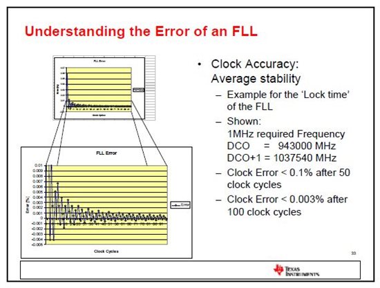
    There is an interesting graphic about the error for short and long time intervals:

    So regarding this documents I think there is a stable high frequency clock possible with a low frequency crystal using FLL technique.

    Ilmars said:

    1. Which devices offer an XT2 oscillator or how to find out using the MSP430 product search on TI website ?

    Use product selector. Usually you have other requirements like I/O pin count, package, flash, peripherals, price. Narrow down pages you have to look into, then check product page and look for "High-Frequency (HF) Crystal" in clock system feature description.

    [/quote]

    Well this is not as helpful as expected. The main feature for me would be a MSP430 device with FLL technique. I found out that this was introduced in the 4xxx series and improved in the 5xxx series. It is maybe hard to find this product with the product selector and would be helpful to have a downloadable database with all features of the MSP430 devices. At least a PDF file with all types and features would be helpful as well. But this is a topic for the TI support team I think.

    Anyway thanks for answering.

  • Karl Dahlmann said:


    FLL is not VCO-based PLL. It's just continuous run-time steering of DCO which is dirty clock source. If you need clean clock, you have to use quartz oscillator.

    Well, I do not agree. You maybe did not understand the problem. I do not have a "dirty" clock source - it is quite stable with an short time accuracy of less than 0.1%.

    [/quote]

    Define short time then. 1 second? What about consecutive 2 clock periods? This is short time, there's your jitter.

    Karl Dahlmann said:
    As I found out, the FLL can do a synchronization of DCO to the low frequency crystal and this would prevent the 10-50 Hz periodic long time jitter caused through small supply voltage changes.

    There's no such thing as long time jitter :)

    It's not supply voltage changes but FLL trying to match target frequency :) Thing is that DCO have discrete frequency steps so FLL-driven DCO __jumps__ between frequencies, output clock virtually never match target frequency in short term, only long term frequency matches target FLL freq for some degree.

    Look at "interesting graphic" which shows1MHz FLL. There's two frequencies mentioned, DCO and DCO+1 which are... not equal to 1MHz. Surprise surprise!! Those are two frequencies DCO will jump between for this case. You can see this in FLL error graph which __never__ reaches straight line at zero level. Of course, in your case there will be other frequency pair. Such jumping inevitably creates clock jitter - some clock periods are shorter (of higher frequency), some are longer (of lower ferquency).

    If in doubt - route clock to pin and look at it using spectrum analyzer.

    In short: forget about FLL. If you need switchable stable clock, then use programmable clock IC.

    Karl Dahlmann said:
    Well this is not as helpful as expected. The main feature for me would be a MSP430 device with FLL technique. I found out that this was introduced in the 4xxx series and improved in the 5xxx series. It is maybe hard to find this product with the product selector

    Did you try? Here you go:

    http://www.ti.com/lsds/ti/microcontroller/16-bit_msp430/5_series/products.page

    As you already noticed, most of 5-series have FLL (maybe all - dunno), so narrow down your search using other chip properties and when you have few then check product description and then datasheet. Easy!

  • Ilmars said:

    As I found out, the FLL can do a synchronization of DCO to the low frequency crystal and this would prevent the 10-50 Hz periodic long time jitter caused through small supply voltage changes.

    There's no such thing as long time jitter :)

    [/quote]


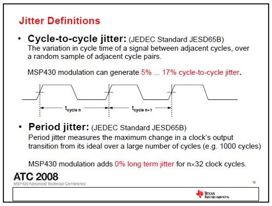
    Well, please read the presentation of Peter Forstner, "Precise Timing with MSP430" or the JEDEC Standard JESD65B. There are the definitions of cycle-to-cycle jitter (short term) and periodic jitter (long term) which can be any time period but normally a larger scale as between a few cycles.

    or JEDEC definition here:

    http://www.jedec.org/sites/default/files/docs/jesd65b.pdf

    Ilmars said:
    In short: forget about FLL. If you need switchable stable clock, then use programmable clock IC.

    I think you either didn't read my posting or did not understand. The statement "forget about FLL" means that you even don't understand what FLL is supposed to be used for. It is just your opinion that it is not useful. Do you really think TI would integrate this mechanism in the higher prices MSP430 controllers if is wouldn't be useful at all ? You should be able to change your mind when you realize the charm of this feature.

    There are two aspects regarding periodic signals like clock signals. First is the accurateness in regular clock cylces. So I know how the feature works with switching between two DCO frequencys to get an average frequency. As I found in the datasheet, the typical difference between two DCO steps are about 8% (ratio 1.08) which means there is a typical error in clock cycle length of +/- 4%.

    So in many applications it doesn't matter if the clock edge vary in this range. In my example of the video signal it will be sampled every 74ns (13.5 MHz). This means that the signal is sometimes measured 3ns earlier (after 71ns) and sometimes 3ns later (77ns). In practice this doesn't matter at all (within this range) and is 100% acceptable.

    This can be even optimized through choosing a higher frequency and divider. If I use double frequency with divider 2 the error is divided by 2 same which will result in a jitter of +/-2% or (+/- 1.5ns). The other point is the repeat accuracy of a signal. Here comes the FLL into game. As found in the graphic above, the long time accuracy of the clock signal is very high and nearly the same as the accuracy where it is locked to (normally a crystal but could be the internal reference REFO as well). In fact this is not suitable for my project as the internal reference is voltage dependend, too. But using a low frequency crystal to control high frequency signals with FLL could be a good alternative.

    As I told cost is a matter of this project as it is for many projects. So my job is to get the maximum effort from the controller to use as less components in project as possible and as cheap as possible. It maybe a better alternative to use a 1.000 MHz crystal which could deliver an internal frequency of 125 kHz which is exactly factor 8 of the horizontal frequency of a video signal with 15.625 kHz and does match to the VGA frequencies of 31.5 / 40 / 50 MHz which can be halfed in my application to 15.75 / 20 / 25 MHz.

    Ilmars said:
    Did you try? Here you go:

    Yes - what do you think ?
    Do you really think I don't know the product selector and did not use it at all ?
    I am a serious developer and use all sources of information and know many different datasheets and application notes of MSP430 devices. The point is, it is not convenient to open dozens of PDF files just to find out if the device supports FLL or not. So this is a hint to the TI support team to offer a more detailed tool or as it best a small database to download and select some more features.

    Of course I have to accept that this is not existing but this doesn't prevent me to make a proposal for it, or does it ?

  • Karl Dahlmann said:
    Well, please read the presentation of Peter Forstner, "Precise Timing with MSP430" or the JEDEC Standard JESD65B. There are the definitions of cycle-to-cycle jitter (short term) and periodic jitter (long term) which can be any time period but normally a larger scale as between a few cycles.

    If you talk about periodic jitter then name it "periodic jitter" next time. In your initial post you say:

    Karl Dahlmann said:
    With this xtal, I can find a value that keeps the drift down to 325us per minute, that's a 5us drift per second. This is what we need.

    Clock frequency drift is wander.

    Karl Dahlmann said:
    I think you either didn't read my posting or did not understand. The statement "forget about FLL" means that you even don't understand what FLL is supposed to be used for. It is just your opinion that it is not useful.

    You are trying to insult, right?

    Statement "forget about FLL" means - I  believe that for video application FLL is no use.

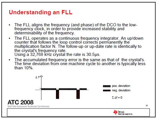
    Please refer to document "understanding FLL" you mention,  about FLL update rate: "Using a 32,768 kHz crystal the rate is 30.5μs". PAL video signal single line time is 64μs. So basically it can happen that half of line have pixel clock which is not that 13.5 MHz as you would like to. Depending on DCO+modulator output frequency granularity FLL frequency change are not necessarily each 30.5μs. Actually this is shown on the same slide graphically. If you test using various chips most probably you will see different pattern of frequency drift or "long term jitter" as you say.

    Good luck.

  • Well I think you are mixing statements of the thread starter with my statements.
    I am not starter of this thread and used it for a related question rather than opening a new thread.
    FLL can be used with other base frequencies as well, it is not fixed to 32.768 kHz (device dependend).
    It can be used with high frequency crystals (XT1) as well.
    So as read in the datasheets a crystal with 4 MHz would be best.
    As stated in the earlier post I plan to use a multiple of the horizontal frequency of 15.625 kHz as reference for FLL.

    Maybe I win a price when publishing a solution for using MSP430 devices with crystal based FLL for video applications.
    :-o

    Please forward to your principal. :-)

  • Karl Dahlmann said:
    Well I think you are mixing statements of the thread starter with my statements.

    So now you know: that starting new thread instead of resurrecting old one is better :D

    Karl Dahlmann said:
    Please forward to your principal. :-)

    Out of arguments? Some posts ago you did have plenty :D

  • No, not out of arguments.
    I meant to forward it to your principal about getting a nice "price" or present for my solution of using MSP430 for video applications.

    :-))


    But nothing more to discuss for now. I will post my experience here in a few weeks with some nice pictures.
    So everybody can see what a MSP430 device can do for you. Hopefully. But I would bet my early morning coffee on it. And you can be sure - this is something I never want to miss.

  • Karl Dahlmann said:
    But nothing more to discuss for now. I will post my experience

    Sure, do it. It will be nice to know for all of us - what you can achieve using just FLL. Hopefully you will succeed and prove that I was wrong assuming that FLL is no good as video pixel clock.

  • Karl Dahlmann said:
    There are the definitions of cycle-to-cycle jitter (short term) and periodic jitter (long term)

    Right. And in the definition of 'periodic jitter', 'long time' is specified with 'e.g. 1000 cycles'. which would be a few µs on a 16MHz clock. Not seconds.:)

    And indeed, both types of jitter are there. The DCO itself uses modulation. It means, the DCO output frequency switches between two frequencies to give the desired average frequency. This is short term jitter. It is as large as 12% (the difference between two DCO steps). The jitter has a pattern that repeats every 32 clock cycles.
    With the limited number of DCO frequencies and the also limited number of modulation patterns, you can get close to but usually never exactly reach the desired target frequency.

    The second one is the FLL adjustment jitter. Other than a PLL, where the VCO is adjusted so that the phase of its output frequency matches the phase of the reference clock, the FLL simply counts clock pulses of the DCO between clock pulses of the reference. if the result is smaller than the desired target factor, the DCO modulation is increased towards the higher DCO frequency, or the DCOx setting in increased.  If it is larger, the DCO is slowed down. This is your long-term jitter and happens on every reference pulse.

    In addition to this, you have a temperature and voltage drift of the DO, which is a drift, no jitter, but since the FLL steers against it, it changes the visible jitter.

    DCO, with or without FLL, is not a clean clock source. It may be sufficient for most purposes, but if you have an application that is sensitive to clock jitter, then an external crystal is the only way.

    The G2 family doesn't support high-frequency crystals. But even though stated otherwise in the datasheet, you can feed an external oscillator signal (TTL square wave) to XTIN and use it. This is of course an undocumented feature and may change in future silicon revisions.

    Almost all other MSP families support HF crystals on XT1 and many, if not most MSPs have an addiitonal XT2 input. of course, if you look at the 'ultra-cheap devices', you won't find all features found on the slightly higher priced standard or workhorse devices.

    Karl Dahlmann said:
    it is not convenient to open dozens of PDF files just to find out if the device supports FLL or not.

    Since the clock system is the same for a whole family, there are only 6 PDFs to read, one for each MSP family. And you'll see that only two families, 4x and 5x (not FR) have an FLL.And 4x requires an external reference clock or crystal while 5x can use any other clock source as reference, including the internal REFO.

    But again, if you need a specific frequency (like an NTSC pixel clock), then I'm sure there are crystals available for exactly this frequency. Use them and be happy. :)

  • First thanks for answering and clarifying.
    Please allow some comments on this.

    Jens-Michael Gross said:
    The DCO itself uses modulation. It means, the DCO output frequency switches between two frequencies to give the desired average frequency. This is short term jitter. It is as large as 12% (the difference between two DCO steps). The jitter has a pattern that repeats every 32 clock cycles.
    With the limited number of DCO frequencies and the also limited number of modulation patterns, you can get close to but usually never exactly reach the desired target frequency.

    So the datasheet gives a typical value of 8% (1.08) between two DCO steps (datasheet of G2553 device) when using 3.0 Volt supply voltage. 12% maybe the worst case depending on RSEL and DCO settings, desired frequency and device type. But I found out that the steps I am working on more to 8% than to 12%.

    Well what is exactly ? Even a crystal is not exactly. More accurate of course. The question is how much accuracy is needed for the application and WHEN. In a TV there are just 2 aspects of the signal that have to be met accurate (more or less):
    1. The sync time to synchronize each line with a length of 64us / 15.625 kHz (for PAL)
    2. The sampling time for each pixel (usually every 74ns / 13.500 MHz)

    The first aspect could be met with a crystal giving a base fequency and FLL. The switching between two frequencys doesn't disturb the second aspect as the clock cycle may vary from +/- 30% on a single cycle but met the condition to be "in time" after 32 cycles and have the difference on each clock period evenly spread. This is what I understand does the modulation and what I can see on the scope. So lets assume that the TV samples every pixel on a fixed time interval and the signal is generated that way, that it is sampled in the middle the sampling point may vary up to +/-45% on a single clock cycle without any visible effects.

    Jens-Michael Gross said:
    But again, if you need a specific frequency (like an NTSC pixel clock), then I'm sure there are crystals available for exactly this frequency. Use them and be happy. :)

    The reason I want to use FLL is to eliminate too much crystals. If I want to support PAL or NTSC video and 2 different VGA solutions (640x480 and 800x600) I need 3 different frequencies, so not just one crystal. So this is the idea where the FLL and a base frequency come into game.

    I am convinced  that I get a clean picture in different VGA and TV resolutions with just one crystal for a high res screen and I am also quite sure that it is possible to generate at least a TV output without FLL and just DCO in low res (320x240) with acceptable result. So the inbuild REFO should be sufficient for this purpose. The old computers from the 80ies did use only ceramic resonators for TV picture with quite much tolerances and produce an acceptable result.

    So I plan to work on a reference application for that which could be used for nearly any MSP430 device with just two resistors to build a 75R video reference signal without any other external components for a low res display or with just a crystal for high res. I am 110% convinced to realize it.

    And lets allow some last words about microcontrollers and it's use. I wonder why you suggest to use an external reference for clock instead of the well sophisticated clock mechanism. It has the same touch as you propose to use an external ADC or DAC or OpAmps or Comparators rather than the inbuild interfaces. So why then should I used a mixed signal controller at all ?

  • To let you get an idea what is possible I show a picture of a ZX81 from Sinclair from 1981 (construction date) still working today. It has a graphic resolution of 256x192 pixel which matches a char resolution of 32 chars x 24 lines.

    Base of clock is just a cheap ceramic resonator with 6.5 MHz and a typical tolerance of about +/- 1%.

  • Karl Dahlmann said:
    Base of clock is just a cheap ceramic resonator with 6.5 MHz and a typical tolerance of about +/- 1%.

    That's the point - 1% tolerance. It does not jump around frequencies, it is just by 1% off, still having quite stable frequency from line to line. In case of FLL things are different :)

  • Ilmars said:

    That's the point - 1% tolerance. It does not jump around frequencies, it is just by 1% off, still having quite stable frequency from line to line. In case of FLL things are different :)

    You didn't get it anyway ?

    This happens if somebody compares apples to oranges or didn't read postings carefully. As I explained above, even variations of up to +/-30% doesn't affect the picture as long as they are base on single clock cylces. And as Jens-Michael said, after 32 cycles there all variations are equalized. So one line consists of 864 clock cycles which means all varitions are eliminated 27 times on every single line.

    I am working for many years now with TV signals and standards - are you sure you are an expert about TV standards ?

  • Karl Dahlmann said:
    You didn't get it anyway ?

    :)

    Karl Dahlmann said:
    And as Jens-Michael said, after 32 cycles there all variations are equalized.

    Seems it's you who did not get it. Because Jens-Michael also said following:

    Jens-Michael Gross said:
    The second one is the FLL adjustment jitter. Other than a PLL, where the VCO is adjusted so that the phase of its output frequency matches the phase of the reference clock, the FLL simply counts clock pulses of the DCO between clock pulses of the reference. if the result is smaller than the desired target factor, the DCO modulation is increased towards the higher DCO frequency, or the DCOx setting in increased.  If it is larger, the DCO is slowed down. This is your long-term jitter and happens on every reference pulse.

    Pay attention to phrase "This is your long-term jitter and happens on every reference pulse". What he says is: __frequency__ is changed on every reference pulse. If you use REFO or 32kHz crystal as reference then FLL output frequency change will occur each 1/32768 second. Now please calculate how many pixels are displayed during 1/32768 seconds if you show 800x600 VGA at 60 Hz? Surprise, huh?

    Karl Dahlmann said:
    I am working for many years now with TV signals and standards - are you sure you are an expert about TV standards ?

    I know enough. Also I don't doubt your knowledge of TV standards as you doubt my knowledge of FLL and clocks as such . What's worse - you doubt my knowledge in field where you are showing questionable expertise yourself.

  • Ilmars said:
    If you use REFO or 32kHz crystal as reference then FLL output frequency change will occur each 1/32768 second. Now please calculate how many pixels are displayed during 1/32768 seconds if you show 800x600 VGA at 60 Hz? Surprise, huh?

    Not surprised and if you follow this thread carefully you will find out that I plan to use a 4 MHz crystal and use 250 kHz as reference which is exactly 16x 15.625 kHz - so FLL will adjust the frequency 16 times per horizontal line. This means 54 pixels are displayed. Could be increased to 500 kHz / 32x 15.625 kHz and adjust every 27 pixel. So I will try different settings to see what gives the best result.

    In fact I get already a good picture without FLL using a 32.768kHz as reference but with a slightly voltage drift. The FLL should just eliminate that voltage drift in a range of a few or a few dozen Hz. I have high claims in my work but after several other tests I find the result acceptable for a low res screen (320x240) and use the FLL with 250kHz reference for a high res screen (640x480 or 800x600).

    I know your opinion about this realisation now but this will not prevent me to do the project in the way I think it is best for my requirements regardless what you think about. So I have no really question any more and so there is no need to reply. I will post the result here at a later time.

  • The problem is that the FLL adjustments won't equalize across multiple scan lines. Especially if you have a drift.

    So you won't get a stable display this way. The pixel positions on each lien won't match the ones of the previous and of the previous frame. It gets better if you ensure that a scanline begins at the beginning of a modulation pattern. This would at least show every 32th pixel at the same position. (unless FLL changes the modulation pattern). But I don't see how this could be possible.
    One way would be to disable modulation. This would keep the DCO stable (virtually no jitter) until it is adjusted by the FLL. However, the frequency might be off by up to 12% then. Still you'd see tearing.

    Another way would be to disable the FLL during screen display, living with the error. Then enable FLL during the gap when no image is shown, to compensate the drift. Or even less often. So you have a stable DCO output during display.

    Still best option is to use a crystal with the exact frequency you need. Which shouldn't be a problem.

    BTW, I remember the ZX81. I didn't have one myself but worked with one. The CPU was 100% busy with the screen output, only doing 'real' work during the gaps. Still a nice device. Especially with the whopping 64k of the extension module.

**Attention** This is a public forum