Other Parts Discussed in Thread: TPS5401, , MSP-FET
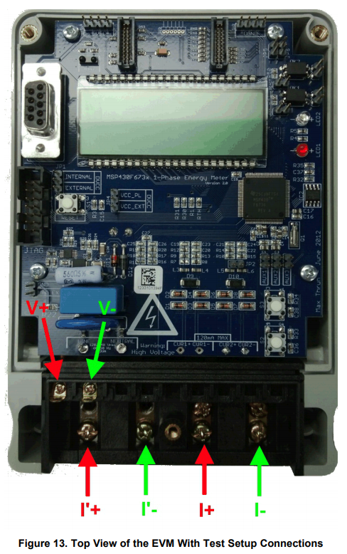
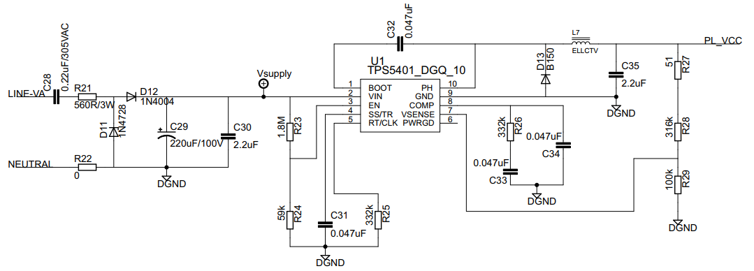
Hi. I just received my EVM430F6736 test module and I do have some questions about it. If I am to supply it 220 VAC, where do I plug on the terminal lugs? because the wires from the LINE/NEUTRAL source is not connected to the terminal lugs. Please help. Also, I noticed that the AGND is shorted with the DGND is it ok? Thank you.