This thread has been locked.

If you have a related question, please click the "Ask a related question" button in the top right corner. The newly created question will be automatically linked to this question.

MSP430F67791A: ADC10 Triggering from SD24 pulse

Part Number: MSP430F67791A

Hi Support,

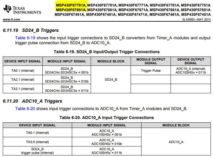
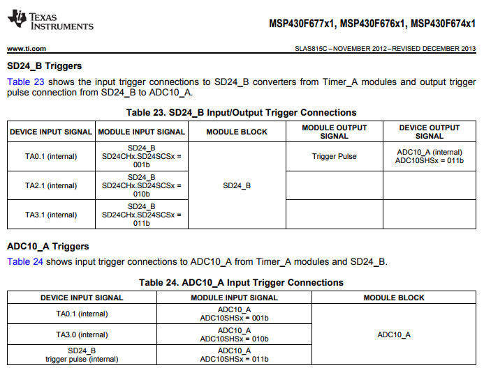
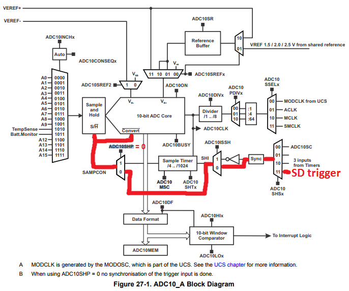
is it possible to trigger ADC10 activities with SD24_B pulse trigger? From SLAS983 it seems that for MSP430F676x1 family this is possible, but seems that it's not the same for MSP430F67791A part.

Can you confirm this?

Thanks and regards,

Alberto

  • Hello Alberto,

    I'm not sure I understand your question. Table 6-20 in the datasheet (SLAS983) clearly shows that the ADC10_A module can accept the SD24_B trigger pulse. At the top of the screenshot below, you can see all of the devices that support this. Am I missing something here?

    Regards,

    James

    MSP Customer Applications

  • There doesn't appear to be any change from the MSP430F67xx non-A devices.

    Regards,

    James

    MSP Customer Applications

  • James,

    thanks for your feedback.

    My customer already tried to configure the ADC10_A with trigger coming from SD24_B as shown below.

    Unfortunately this is not working. In fact the ADC10 interrupt is not invoked after SD24 request.

    They tried different settings but without success. They are only able to have ADC10SHSx = 00b working. Looking into note 29.2.12 of SLAU208P Manual, it seems that trigger generator is limited to F676x1 family: 

    Can you kindly confirm me this will be available for 6779x as well?

    Thanks and regards,

    Alberto

  • Hello Alberto,

    I suspect that this NOTE in our User's Guide may need updated to include the MSP430F677x(A) devices as well. Can you share the code that the customer used for triggering the ADC10 by the SD24 trigger?

    I'll check internally to confirm that this feature is supported by the F677x(A) devices and let you know.

    Regards,

    James

    MSP Customer Applications
  • James,

    please find in attachment code example I received from customer.

    This is their desired configuration, including 3 SD24 channels, 6 ADC10 channels acquired in sequence.

    I look forward to read your feedback.

    thanks for your support,

    Regards,

    Alberto

    Project main test_trigger.zip

  • Hello Alberto,

    Thanks for sharing their code. In 'main.c', I see a line of code with a comment that says "this is ok". Can you check what they mean by this? Did this configuration of ADC10CTL1 work and the uncommented line of code with the comment "where am i wrong" not work?

     ADC10CTL0 |= ADC10SHT_2 | ADC10MSC | ADC10ON;                                 // 16ADCclks, MSC (Multiple SampleConversion), ADC ON    (6.5us tra i campionamenti - ~13us ritardo tra fase 1 e fase 3)
      // this is OK
      //ADC10CTL1 = ADC10SHP | ADC10CONSEQ_1 | ADC10SSEL_3 | ADC10DIV_5 | ADC10SHS_0; // pulse sample mode, single sequence, CLOCK select SMCLK /5 (freq.deve essere tra 0.45 e 5.5 MHz) select triggers ADC10SC bit
      // enable  ADC10SC on interrupt TIMER0_A0_ISR                                                         /
      
      // where am I wrong?
      ADC10CTL1 = ADC10SHP | ADC10CONSEQ_1 | ADC10SSEL_3 | ADC10DIV_5 | ADC10SHS_3;   // ????????????????
      //

    In the meantime, I'll assume this is the case and compare the two configurations. Let me also point out that Errata ADC42 may be causing an issue here if the customer is triggering the ADC while it's busy.

    Regards,

    James

    MSP Customer Applications

  • Looking at these two lines more closely, I see that the only difference is ADC10SHSx. This makes sense based on your initial description.

    Regards,

    James

    MSP Customer Applications
  • I think I've found the issue. They're setting the ADC10SHP bit, which ignores the SD trigger. Have them remove this and see if the ADC10 gets triggered by the SD trigger.

    ADC10CTL1 = ADC10CONSEQ_1 | ADC10SSEL_3 | ADC10DIV_5 | ADC10SHS_3;

    When ADC10SHP is set to zero, you can see in the Figure 27-1 from the User's Guide that the SD trigger should initiate the ADC sample.

    Regards,

    James

    MSP Customer Applications

  • Hello Alberto,

    Did this resolve the customer's issue? If so, please mark the thread accordingly. I'll be closing the thread shortly.

    Regards,

    James

    MSP Customer Applications
  • James,

    just received customer feedback.
    The solution purposed is not what they need. In fact they would like to have a situation similar to SLAA621C, but they are not able to launch the 6 ADC10 conversions with a single trigger input. They are even not able to trigger this using TA0.1 neither SD24 pulse.
    The only way they have to start triggering is using bit ADC10SHSx=0, enabling SHI signal and then "Sample timer" module finally launches the conversions.
    They can finally survive with this method, but the ones described above would be preferred methods.
    Please let me know if you have further inputs.
    regards,
    Alberto
  • Hello Alberto,

    I suspect that they aren't configuring the trigger generator correctly. Thus, even if they configure the ADC10 module to get triggered by the SD trigger, it wouldn't work correctly. If the trigger generator is configured the same as the converters and is started together with the converters, it can trigger the ADC10 module synchronous with the conversion (that is, decimation) of the SD24_B converters.

    See Section 29.2.12 in the MSP430x5xx/x6xx User's Guide for more details about this, including the SD24_B Trigger Generator Block Diagram (attached in one of my earlier posts above). The registers shown below would need to be configured, which they probably aren't doing.

    • SD24BTRGCTL
      • SD24TRGIE
      • SD24TRGIFG
      • SD24SNGL
      • SD24SCSx

      • SD24SC
    • SD24BTRGOSR
    • SD24BTRGPRE

    Have they downloaded the source code from the Implementation of a Low-Cost Three-Phase Electronic Watt-Hour Meter Using the MSP430F67641 app note (SLAA621) to see how this is done? I would strongly recommend this. They can search throughout the project and find where these registers are getting configured.

    After opening the project in IAR, I quickly found some of these registers in the 'metrology-setup.c' and 'metrology-setup.c' files.

    Regards,

    James

    MSP Customer Applications

  • Hello Alberto,

    Did this answer your question? If so, please click the green "This Resolved My Issue" button.

    Regards,

    James

    MSP Customer Applications

**Attention** This is a public forum