This thread has been locked.

If you have a related question, please click the "Ask a related question" button in the top right corner. The newly created question will be automatically linked to this question.

CCS/MSP430FR5969: Understanding MPU

Part Number: MSP430FR5969
Other Parts Discussed in Thread: MSP430FR5959

Tool/software: Code Composer Studio

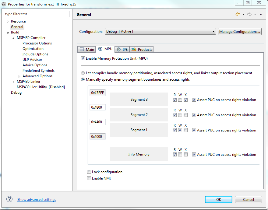
I thought it would be nice if overwriting code would kick over the processor.. So I started looking at the MPU. There are various bits and pieces of information on how it's supposed to work. However I'm a bit confused just how automagically it works. It's implied that it should "just work" without doing anything as long as you have the "Enable MPU" ticked in the CCS general properties of the project. I'm not quite convinced however.. 

This is what the default linker file's MPU bits look like for MSP430FR5969:

#ifdef _MPU_ENABLE
   #define MPUPW (0xA500)    /* MPU Access Password */
   #define MPUENA (0x0001)   /* MPU Enable */
   #define MPULOCK (0x0002)  /* MPU Lock */
   #define MPUSEGIE (0x0010) /* MPU Enable NMI on Segment violation */

   __mpu_enable = 1;
   // Segment definitions
   #ifdef _MPU_MANUAL // For custom sizes selected in the GUI
      mpu_segment_border1 = _MPU_SEGB1 >> 4;
      mpu_segment_border2 = _MPU_SEGB2 >> 4;
      mpu_sam_value = (_MPU_SAM0 << 12) | (_MPU_SAM3 << 8) | (_MPU_SAM2 << 4) | _MPU_SAM1;
   #else // Automated sizes generated by Linker
      #ifdef _IPE_ENABLE //if IPE is used in project too
         //seg1 = any read + write persistent variables
         //seg2 = ipe = read + write + execute access
         //seg3 = code, read + execute only
         mpu_segment_border1 = fram_ipe_start >> 4;
         mpu_segment_border2 = fram_rx_start >> 4;
         mpu_sam_value = 0x1573; // Info R, Seg3 RX, Seg2 RWX, Seg1 RW
      #else
         mpu_segment_border1 = fram_rx_start >> 4;
         mpu_segment_border2 = fram_rx_start >> 4;
         mpu_sam_value = 0x1513; // Info R, Seg3 RX, Seg2 R, Seg1 RW
      #endif
   #endif
   #ifdef _MPU_LOCK
      #ifdef _MPU_ENABLE_NMI
         mpu_ctl0_value = MPUPW | MPUENA | MPULOCK | MPUSEGIE;
      #else
         mpu_ctl0_value = MPUPW | MPUENA | MPULOCK;
      #endif
   #else
      #ifdef _MPU_ENABLE_NMI
         mpu_ctl0_value = MPUPW | MPUENA | MPUSEGIE;
      #else
         mpu_ctl0_value = MPUPW | MPUENA;
      #endif
   #endif
#endif

To start with, from the linker file it appears that without defining _MPU_ENABLE_NMI somewhere, MPU essentially does nothing. Is there a GUI tickbox somewhere for that? It seems to me that there would be only one protected memory region called fram_rx_start. So actually splitting code between FRAM and FRAM2 is not working as intended? The default linker file splits code between FRAM2 and FRAM. "fram_rx_start" seems to be set automagically at the end of the IPENCAPSULATED_MEMORY. Since I don't have IPE active, would the fram_rx_start get assigned to e.g. beginning of FRAM2?

If the IDE is actually as clever as it implies, it seems that it would be enough to put _MPU_ENABLE_NMI to "Predefined Symbols" and add a line to NMI ISR as in the MPU driverlib example?

Alternatively I could go the whole hog and  define my own memory regions in the linker file and so on. Which is actually what I did already before I started wondering just how is the MPU getting set up exactly.. Do the flags on MEMORY actually do anything? I modified the linker file to allocate 4+16kB for code/constants/ISR like so:

MEMORY
{
    SFR                     : origin = 0x0000, length = 0x0010
    PERIPHERALS_8BIT        : origin = 0x0010, length = 0x00F0
    PERIPHERALS_16BIT       : origin = 0x0100, length = 0x0100
    RAM                     : origin = 0x1C00, length = 0x0800
    INFOA                   : origin = 0x1980, length = 0x0080
    INFOB                   : origin = 0x1900, length = 0x0080
    INFOC                   : origin = 0x1880, length = 0x0080
    INFOD                   : origin = 0x1800, length = 0x0080
    FRAM                    : origin = 0x4400, length = 0xAF80
    FRAMRO  (RXI)			: origin = 0xF380, length = 0x0C00
    FRAMRO2 (RXI)           : origin = 0x10000,length = 0x4000

It would be again implied that setting (RXI) would keep that region "hands off" automagically, but.. On subject of flags, Initialize flag I'm not sure about. Intiialize when? After boot? During flashing when the #pragma PERSISTENT stuff gets initialized once?

  • Hi Olli,

    At first, trying to decipher how the linker file initializes the MPU and partitions memory can be very confusing, as you've already discovered. Additionally, a lot of variables seem to get set "automagically" but I'll try to breakdown how everything works.

    There are three ways you can setup the MPU but let's start with how the compiler will handle it by default:

    By default the compiler will create 3 memory sections with the following permissions and addresses

    1. Segment 1: Persistent Variables, I/O buffer, Dynamic memory allocation
      1. NOTE: This is only if these variables exist in your code. Otherwise length = 0
      2. Permissions: Readable and Writable
      3. Starting Address: Start of FRAM
      4. Ending Address: Start of Segment 2 (aligned to 0x0400)
    2. Segment 2: Intellectual Property Encapsulated (IPE) Code
      1. NOTE: This is only if IPE is enabled. Otherwise the section length = 0.
      2. Permissions: Readable, Writable, and Executable
      3. Starting Address: End of Segment 1 or start of FRAM if Seg1 length = 0.
      4. Ending Address: Start of Segment 3 (aligned to 0x0400)
    3. Segment 3: Code
      1. Permissions: Readable and Executable
      2. Starting Address: End of Segment 2, end of Segment 1 if Seg2 length = 0, or beginning of FRAM if both Seg 1 and Seg 2 length = 0
      3. Ending Address: End of FRAM2


    All these segment boundaries are determined "automagically" by this portion of code in the linker file:

    GROUP(RW_IPE)
    {
    
    GROUP(READ_WRITE_MEMORY)
    {
    
    .TI.persistent : {} /* For #pragma persistent */
    .cio : {} /* C I/O Buffer */
    .sysmem : {} /* Dynamic memory allocation area */
    } PALIGN(0x0400), RUN_START(fram_rw_start)
    
    GROUP(IPENCAPSULATED_MEMORY)
    {
    
    .ipestruct : {} /* IPE Data structure */
    .ipe : {} /* IPE */
    .ipe_const : {} /* IPE Protected constants */
    .ipe:_isr : {} /* IPE ISRs */
    } PALIGN(0x0400), RUN_START(fram_ipe_start) RUN_END(fram_ipe_end) RUN_END(fram_rx_start)
    
    } > 0x4000

    The RUN_START macro assigns the starting address of the respective group to the variable passed to it. Similarly the RUN_END macro assigns the end address of the respective group to the variable passed to it. Finally the PALIGN macro aligns the memory to the boundary passed to it. So for example, let assume that you have 500kB of persistent variables, 2kB of IPE data, and 10kB of code. The variables seen above would be assigned as follows if using the MSP430FR5959:

    • fram_rw_start = 0x4400
    • fram_ipe_start = 0x4800 (due to 0x0400 alignment)
    • fram_rx_start = 0x5000

    This would then make the segment boundaries as follows:

    • Segment 1 (RW): 0x4400 to 0x47FF
    • Segment 2 (RWX): 0x4800 to 0x4FFF
    • Segment 3 (RX): 0x5000 to 0x13FFF

    This is would then be setup by this code in the linker file:

    // Segment definitions
    #ifdef _MPU_MANUAL // For custom sizes selected in the GUI
    mpu_segment_border1 = _MPU_SEGB1 >> 4;
    mpu_segment_border2 = _MPU_SEGB2 >> 4;
    mpu_sam_value = (_MPU_SAM0 << 12) | (_MPU_SAM3 << 8) | (_MPU_SAM2 << 4) | _MPU_SAM1;
    #else // Automated sizes generated by Linker
    #ifdef _IPE_ENABLE //if IPE is used in project too
    //seg1 = any read + write persistent variables
    //seg2 = ipe = read + write + execute access
    //seg3 = code, read + execute only
    mpu_segment_border1 = fram_ipe_start >> 4;
    mpu_segment_border2 = fram_rx_start >> 4;
    mpu_sam_value = 0x1573; // Info R, Seg3 RX, Seg2 RWX, Seg1 RW
    #else
    mpu_segment_border1 = fram_rx_start >> 4;
    mpu_segment_border2 = fram_rx_start >> 4;
    mpu_sam_value = 0x1513; // Info R, Seg3 RX, Seg2 R, Seg1 RW
    #endif
    #endif

    You'll notice that when IPE is enabled, this code set's the segment 1 boundary to the beginning of the IPE section, and the segment 2 boundary to the beginning of the code segment. This effectively creates 3 memory sections as follows:

    • 0x4400 to fram_ipe_start
    • fram_ipe_start to fram_rx_start
    • fram_rx_start to end of FRAM2

    You'll also notice that if IPE is disabled that the mpu_segment_border1 = mpu_segment_border2. This is done purposefully and effectively sets the length of the IPE segment (Segment 2) to 0. In this scenario 3 sections are created as follows:

    • 0x4400 to fram_rx_start
    • fram_rx_start to fram_rx_start (length of 0)
    • fram_rx_start to FRAM2 end

    Additionally, when allowing the compiler to setup the MPU, by default the Non-Maskable Interrupt (NMI) that can be generated by the MPU is disabled. This does not mean that the MPU is not protecting these memory sections. It only means that no interrupt will be generated if an access violation is attempted but the memory is still protected from erroneous access. As you mentioned, you can enable NMI's while also letting the compiler handle the MPU setup by predefining _MPU_ENABLE_NMI. In this case, you'll need to provide an interrupt service routine for the NMI vector in your code.

    Finally, you'll notice that this code sets the permissions for the sections allocated by the compiler:

    mpu_sam_value = 0x1513; // Info R, Seg3 RX, Seg2 R, Seg1 RW

    You can and should change this to meet the requirements of your application.

    The second way to setup the MPU is using by selecting the "Manually specify memory segment boundaries and access rights" radio button in the project properties:

    Here you can setup the boundaries and access rights to whatever you need for your application. The only difference is that the sections might not optimized to the size necessary for each segment like the compiler handles it. Additionally, you can select the "Lock configuration" and/or the "Enable NMI" checkboxes to predefine the _MPU_LOCK and the _MPU_ENABLE_NMI definitions automatically.

    The last way to setup the MPU is in your code at the start of execution. This is difficult but can be done by carefully following the User Guide to setup the registers for your applications needs.

    Finally, I'm not familiar with the RXI flag and I'm not sure what you mean by this question, could you elaborate more please:

    Olli Mannisto said:
    On subject of flags, Initialize flag I'm not sure about. Intiialize when? After boot? During flashing when the #pragma PERSISTENT stuff gets initialized once?

    Best regards,
    Caleb Overbay

  • The initialize flag is found in the MSP430 Assembly Language reference SLAU131 chapter 8.5.4.2.

    attr specifies one to four attributes associated with the named range. Attributes are optional;
    when used, they must be enclosed in parentheses. Attributes restrict the allocation of
    output sections into certain memory ranges. If you do not use any attributes, you can
    allocate any output section into any range with no restrictions. Any memory for which no
    attributes are specified (including all memory in the default model) has all four attributes.
    Valid attributes are:

    R specifies that the memory can be read.
    W specifies that the memory can be written to.
    X specifies that the memory can contain executable code.
    I specifies that the memory can be initialized

    So therefore constructing my own memory partitioning I specified

    FRAMRO  (RX)            : origin = 0x4400, length = 0x0C00
    FRAM         			: origin = 0x5000, length = 0xAF80
    FRAMRO2 (RX)            : origin = 0x10000,length = 0x4000

    Now do those flags actually do anything? 

    From your example you're allocating majority of the FRAM for code (RX). What I personally tried to achieve was to create two read-only segments in the beginning of the 48kB block of FRAM and all of the 16kB block. I wanted to avoid declaring the "in between" part as RX as it contains a lot of "other" stuff i.e. signatures and interrupt vectors. I think those should be RO in fact, neither contains code and neither should be manipulated at runtime. 

    Based on your explanation I'll remove those manually allocated segments as I'd have to babysit the code usage. Is this actually written down anywhere? For example SLAA685, SLAA628 and SPMA044A all address the memory protection but do not explain how it works automagically in code composer. Granted, some of those are fairly old e.g. SPMA044A is from 2012. 

    Without PUC or NMI there's no indication of access fault which is a hallmark of runaway pointer which are rather difficult to debug on best case.. So I better assign NMI to kick over the CPU and increment watchdog flag:

            case 0x0E:                              //MPUSEG2IFG
                // Clear violation interrupt flag
                SYSNMIflag =1;                      // Set flag
                myconfig_rw.watchdog_l++;
                if(!myconfig_rw.watchdog_l){
                    myconfig_rw.watchdog_h++;
                }
                /*
                 * Goodbye cruel world!
                 */
                PMM_trigPOR();
                break;

  • Hi Olli,

    The flags you are referencing are only used at compile time to let the compiler know where to allocate code, read -only, and writable memory. It doesn't actually setup the MPU. So when using the flags and not setting up the MPU, the memory would remain unprotected.

    Also, I believe the interrupt vectors need to be executable to operate properly and this is why the default setup gives them RX permissions. The concept behind the default setup is that the code would typically consume the most memory in your application and you want to keep it from being split between two sections. That's why the larger portion of memory (FRAM2) is included in the code section.

    Finally, I don't believe that the way the linker file handles the MPU settings is documented in a User's Guide or something similar. I'll give this feedback to our internal team. I'd also like to point out that SPMA044A does not apply to the MSP430 line of microcontrollers.

    Best regards,
    Caleb Overbay
  • In MPS430FR5969 the FRAM2 is in fact 16kB and FRAM is 48kB. Code does indeed get split between FRAM2 and FRAM with majority being in FRAM2. Should I manipulate the linker file to prefer FRAM over FRAM2 for code and prefer FRAM2 for constants and persistent data?

    After a few false starts, I got the MPU NMI working as intended with manually constructed 0x01000 pointer write triggering it. I spent a while before I understood that COMPILER defines/macros do not carry over to LINKER. So _MPU_ENABLE_NMI has to be defined explicitly for linker.
  • Hi Olli,

    My apologies I was incorrect when saying FRAM2 was the larger portion of memory. In most MSP430 devices that have an upper address space, FRAM2 is larger than FRAM, but you've pointed out this is no the case here. It's still ok to let your code be split between FRAM and FRAM2. When I previously said you didn't want your code split between two "sections" I should have said segments instead. You really don't want your code split between two MPU segments and this is why the largest segment is the code segment.

    I'm glad to hear you were able to get things working correctly. Let me know if you have any more questions!

    Best regards,
    Caleb Overbay

**Attention** This is a public forum