This thread has been locked.

If you have a related question, please click the "Ask a related question" button in the top right corner. The newly created question will be automatically linked to this question.

Compiler/MSP430FR2111: In the LPM3, ADC sample is abnormal on A0 Pin?

Part Number: MSP430FR2111


Tool/software: TI C/C++ Compiler

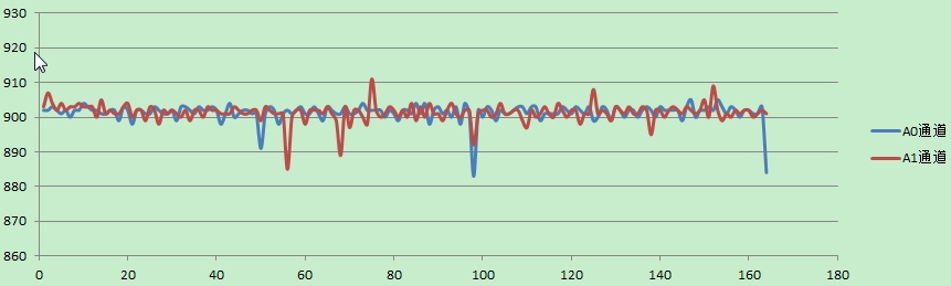
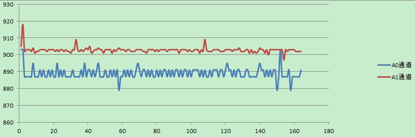
Good Day, I used Sequence of Channels Mode to sample A0, A1 channels. The same voltage is applied to the A0,A1 pins. However, the  sample values is different in LPM3   and the sample values is same in active mode . Why is the reason? The codes is following:

INT16U g_Result[2][164] ={0} ;  // A0 g_Result[0],A1 g_Result[1]
INT8U g_AdcCount;
INT8U g_ResutNum;
 
int main(void) 
{
    WDTCTL = WDTPW | WDTHOLD;  
    InitSystemClock();	//MCLK =8MHz, SMCLK = off ,REFO(~32768Hz) is source of  ACLK = 32768Hz
    
    P1SEL0 |= BIT0 + BIT1;
    P1SEL1 |= BIT0 + BIT1;
    PM5CTL0 &= ~LOCKLPM5; 
    
    ADCCTL0 = ADCSHT_4| ADCMSC ;                    
    ADCCTL1 = ADCSHP  | ADCSSEL_0 | ADCCONSEQ_1;    //ADCSC Trriger,Sequence of Channels Mode
    ADCCTL2 = ADCRES_1 ;                            
    ADCMCTL0 = ADCSREF_1 | ADCINCH_1;               //REF =1.5V 
    ADCIE |= ADCIE0;   
    
    PMMCTL0_H = PMMPW_H;                    
    PMMCTL2 |= INTREFEN ;                   
    while(!(PMMCTL2 & REFGENRDY)); 
    
    
    TB0CCTL0 |= CCIE;                                             
    TB0CCR0 = 7;                                  // set 244us        
    TB0CTL = TBSSEL__ACLK | MC_1 | TBCLR;  
    
    __bis_SR_register(GIE|LPM3_bits );
    
    while(1);
    
}

#pragma vector = TIMER0_B0_VECTOR
__interrupt void Timer_B (void)
{
    g_AdcCount = 1;
    if(g_ResutNum > 163)
    {
        g_ResutNum = 0;
    }
    ADCCTL0 |= ADCON| ADCENC | ADCSC;      //ADC start                            
}

#pragma vector=ADC_VECTOR
__interrupt void ADC_ISR(void)
{
    switch(__even_in_range(ADCIV,ADCIV_ADCIFG))
    {
        case ADCIV_NONE: 
            break;                              
        case ADCIV_ADCOVIFG: 
            break;             
        case ADCIV_ADCTOVIFG: 
            break;            
        case ADCIV_ADCHIIFG: 
            break;             
        case ADCIV_ADCLOIFG: 
            break;             
        case ADCIV_ADCINIFG: 
            break;             
        case ADCIV_ADCIFG:
     
            g_Result[g_AdcCount][g_ResutNum] = ADCMEM0;

            if(g_AdcCount == 0)
            {
                g_ResutNum++;
            }
            else
            {
                g_AdcCount--;
            }
           
            break;                                             
        default: 
            break; 
    }  
}

the data of A0,A1 is following:

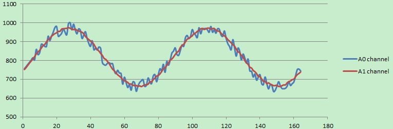
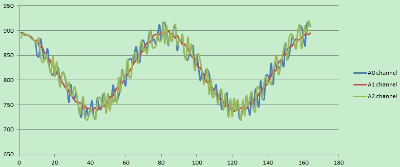
When I change "__bis_SR_register(GIE|LPM3_bits );" to "__bis_SR_register(GIE);" ,  the CPU is always active. The samples datas is normally , the data graph :

  • Hi
    You can refer to this code
    #include <msp430.h>
    #include<stdint.h>
    unsigned int g_Result[2][163] ={0} ; // A0 g_Result[0],A1 g_Result[1]

    unsigned char g_AdcCount=0;
    unsigned char g_ResutNum=0;

    int main(void)
    {
    WDTCTL = WDTPW | WDTHOLD;
    // InitSystemClock(); //MCLK =8MHz, SMCLK = off ,REFO(~32768Hz) is source of ACLK = 32768Hz

    P1SEL0 |= BIT0 + BIT1;
    P1SEL1 |= BIT0 + BIT1;
    PM5CTL0 &= ~LOCKLPM5;

    ADCCTL0 = ADCSHT_15| ADCMSC|ADCON ;
    ADCCTL1 = ADCSHP | ADCSSEL_0 | ADCCONSEQ_1; //ADCSC Trriger,Sequence of Channels Mode
    ADCCTL2 = ADCRES_1 ;
    ADCMCTL0 = ADCSREF_1 | ADCINCH_1; //REF =1.5V
    ADCIE |= ADCIE0;

    PMMCTL0_H = PMMPW_H;
    PMMCTL2 |= INTREFEN ;
    while(!(PMMCTL2 & REFGENRDY));


    TB0CCTL0 |= CCIE;
    TB0CCR0 = 70; // set 244us
    TB0CTL = TBSSEL__ACLK | MC_1 | TBCLR;

    __bis_SR_register(GIE|LPM3_bits );
    // __bis_SR_register(GIE );

    while(1);

    }

    #pragma vector = TIMER0_B0_VECTOR
    __interrupt void Timer_B (void)
    {
    g_AdcCount=0;
    if(g_ResutNum > 163)
    {
    g_ResutNum = 0;
    }

    ADCCTL0 |= ADCENC | ADCSC; //ADC start
    }

    #pragma vector=ADC_VECTOR
    __interrupt void ADC_ISR(void)
    {
    switch(__even_in_range(ADCIV,ADCIV_ADCIFG))
    {
    case ADCIV_NONE:
    break;
    case ADCIV_ADCOVIFG:
    break;
    case ADCIV_ADCTOVIFG:
    break;
    case ADCIV_ADCHIIFG:
    break;
    case ADCIV_ADCLOIFG:
    break;
    case ADCIV_ADCINIFG:
    break;
    case ADCIV_ADCIFG:

    g_Result[g_AdcCount][g_ResutNum] = ADCMEM0;


    if(g_AdcCount == 0)
    {
    g_ResutNum++;
    }

    g_AdcCount++;


    break;
    default:
    break;
    }
    }
  • Hi,
    Thanks for your help. I found the reason is "ADCSHT_15" .If I set" ADCCTL0 = ADCSHT_4| ADCMSC|ADCON ; " ,the A0 channel datas is wrong . " ADCCTL0 = ADCSHT_15| ADCMSC|ADCON ; " could make A0 sample normal.
    In programming ,how to rightly select the value of ADCSHT_x?
  • Hi
    The problem is you do no give enough time for CPU to read the first data. If the sample hold time set to short. The second ADC conversion will be finished at the period that the CPU is reading the first data. So you may miss the data at this case.
    Best regards
    Gary
  • hello,

     Thanks for your help. But I am using the code to sample  AC signal (A0,A1 has same AC signals), A0 channel  doesn’t  work well .the datas as following

     I try to change the value of ADCSHT_x, it still doesn't work well . So I guess that some wrong things is in  the PCB electric circuits. I  exchanges the A0 channel's electric circuits  with A1 channel's electric circuits.  But  the phenomenon doesn't be improve, A0 channel's datas still don't well .  Then , I don't think any reasons without MCU. Could you give me some advises?

    Best regards

    Jent

  • Hi Jent,

    some thoughts about your issue... could you please try each of this steps if they will fix your issue:
    - please set REFON bit in REFCTL0 to keep reference voltage on
    - would it possible to change A0 from even to an odd channel e.g. A3 or A5 just to see if this will fix this issue

    Best regards,
    Tobias

  • Hi Jent,
    Please help to check Tobias' questions as well as Winter Yu's question as follows.
    ========================================================
    What's the stage of customer's project? In mass production or development?
    What's the failure rate? How many units did you test? Is it only observed on some units (e.g. can only be reproduced on already known failing customer return units)?
    What's the ADC reference voltage? Did you find a related reference voltage or power supply change when entering LPM3?

    Many thanks.
    Regards,
    Young
  • Many thanks for you ,

    Winter Yu's questions:

    1. The project is in small-scale production stage about 500 devices.

    2. Only three units were tested now, others has not been tested.

    3. ADC reference voltage is MCU's internal reference 1.5V, Nothing is changed during LPM3 mode.

    Tobias's questions:

    1. I am watching EXTREFEN bit ,INTREFEN bit in PMMCTL2 register, They didn't change  to 0h during  single step debug.

    2. I try to use A0 ,A2 sample the same AC signal (connect A0 and A2 channel with wire) , the A1 channel  keep the orignal .  A0 and A2 channels has same  phenomenon ,the datas graph:

    Then , I try to use A2 channel instead of A0 channel (connect the PCB circuit of A0 to A2 channel, and  disconnect to A0 channel ), the A1 channel keep  the orignal . the datas is following:

    Accroding  to the above, I guess that the A0 channel of MCU has some problems.

    Best regards,

    Jent

  • Hi Jent,
    thanks for doing this experiment which brings us closer to the root cause and a solution.
    As far as I know, A0 and A2 are using the same internal path. So if changing from A0 to A2 fixes this issue, it points for me a PCB issue. My intention was to change to A3 or A5 which would be a different internal path. So good that we had a misunderstanding here.

    It points for me even more on a PCB issue as you mentioned that signal is still bad on A2 if you still have A0 connected. So could you please check the PCB on A0? Are the anything else connect, long wires or wires with dead ends e.g.

    Best regards,
    Tobias

**Attention** This is a public forum